
iMeshbean 08349
iMeshbean 40/60 PSI Well Pump Pressure Switch Instruction Manual
Model: 08349
1. Introduction
This manual provides comprehensive instructions for the installation, operation, and maintenance of your iMeshbean 40/60 PSI Well Pump Pressure Switch. Please read this manual thoroughly before installation and use to ensure safe and efficient operation.
The iMeshbean pressure switch is designed to automatically control the start and stop of a water pump based on system pressure. It is suitable for various water pump applications, including deep well pumps, self-priming pumps, and jet pumps.
2. Safety Information
- Always disconnect power to the pump before installing, adjusting, or servicing the pressure switch.
- Installation should be performed by a qualified electrician or plumber in accordance with local electrical and plumbing codes.
- Ensure proper grounding to prevent electrical shock.
- Do not exceed the specified electrical ratings of the switch.
- Wear appropriate personal protective equipment (PPE) during installation and maintenance.
3. Product Specifications
| Feature | Specification |
|---|---|
| Pressure Setting | 40-60 PSI (Adjustable) |
| Cut-In Pressure (Min) | 20 PSI |
| Cut-Off Pressure (Max) | 120 PSI |
| Fluid Connection | 1/4" NPSF Internal |
| IP Grade | IP20 |
| Frequency | 50/60 Hz |
| Horsepower Rating (1-Phase) | 2HP-115VAC, 3HP-230VAC |
| Material | Steel and Plastic |
For a visual overview of the specifications, refer to the image below:

This image displays the key specifications of the pressure switch, including pressure settings, electrical ratings, and IP grade.
4. Product Components and Diagram
Familiarize yourself with the main components of the pressure switch before installation.

This diagram illustrates the internal and external components of the pressure switch, indicating connection points and adjustment nuts.
- 1 & 3: Power Cable Connection Terminals
- 2 & 4: Pump Connection Terminals
- 5: Larger Range Adjustment Nut
- 6: Differential Adjustment Nut
- 7 & 8: Ground Screws
A detailed view of the switch's construction:

This image shows close-up views of the pressure control button, internal springs, and connection points, highlighting the robust construction.
5. Installation (Setup)
Follow these steps for proper installation of the pressure switch:
- Disconnect Power: Ensure all power to the well pump system is turned off at the circuit breaker.
- Mounting: The pressure switch typically mounts directly to a 1/4" NPT female port on the pump or pressure tank.
- Fluid Connection: Connect the 1/4" NPSF internal fluid connection of the switch to the corresponding port on your water system. Use thread sealant tape for a watertight seal.
- Electrical Wiring:
- Connect the power cable to terminals 1 and 3 as indicated in the diagram.
- Connect the pump motor wires to terminals 2 and 4.
- Connect the ground wire to the ground screws (7 & 8).
- Ensure all connections are secure and insulated.
- Verify Connections: Double-check all electrical and plumbing connections before restoring power.
The switch features a 1/4" Female NPT connection for straightforward integration:
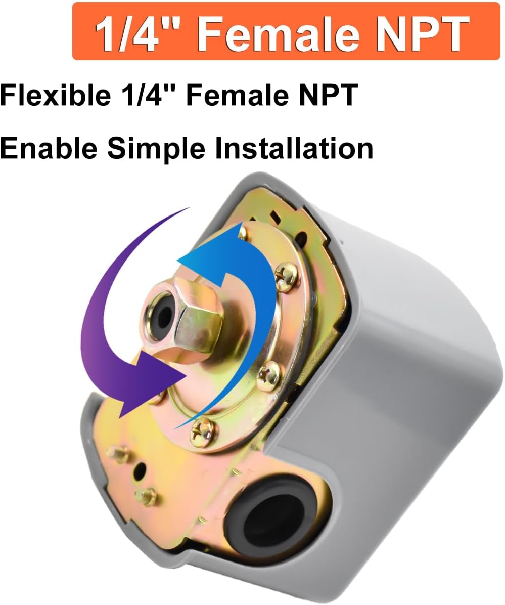
This image highlights the 1/4" Female NPT connection, designed for easy and secure installation into your water system.
6. Operation and Pressure Adjustment
The pressure switch automatically turns the pump on and off based on the set pressure range. The factory setting is 40-60 PSI.
Adjusting Pressure Settings:
The switch features a double-spring design for precise adjustment of cut-in and cut-out pressures. Always adjust the RANGE nut first, then the DIFFERENTIAL nut.
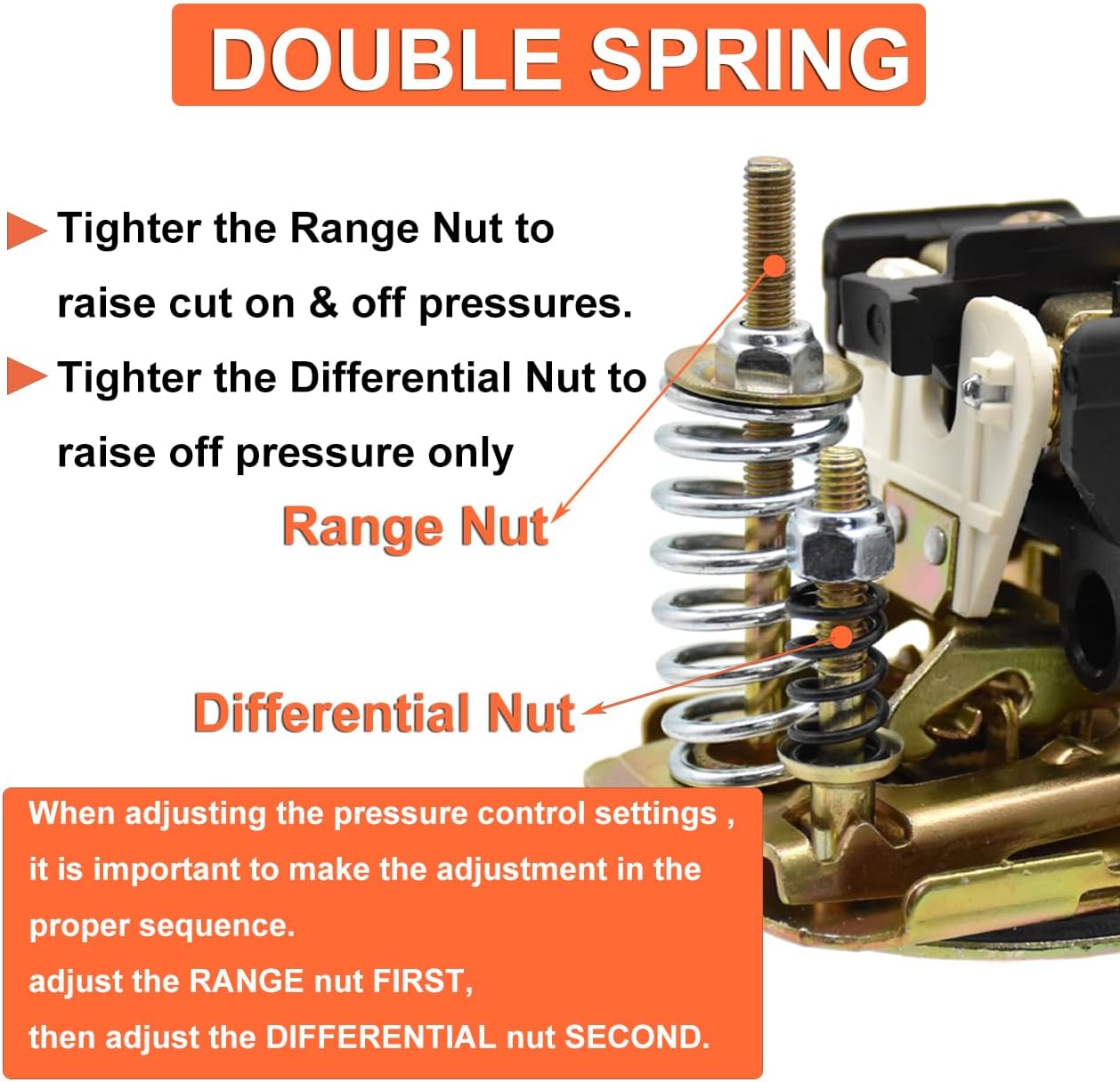
This image illustrates the double spring mechanism, showing the 'Range Nut' and 'Differential Nut' used for adjusting the pressure settings.
- Range Nut (Larger Spring): Tightening the larger Range Nut (5) will raise both the cut-in and cut-out pressures simultaneously. Loosening it will lower both.
- Differential Nut (Smaller Spring): Tightening the smaller Differential Nut (6) will raise only the cut-out pressure, increasing the pressure differential. Loosening it will lower the cut-out pressure, decreasing the differential.
Important: When adjusting the pressure control settings, it is crucial to follow the correct sequence: adjust the RANGE nut FIRST, then adjust the DIFFERENTIAL nut SECOND.
After adjustment, monitor the pump's operation to ensure it cycles correctly within your desired pressure range.
7. Maintenance
The iMeshbean pressure switch is designed for durability and reliability. Regular maintenance can extend its lifespan:
- Periodic Inspection: Annually inspect the switch for any signs of wear, corrosion, or loose connections.
- Cleanliness: Keep the switch free from dirt, dust, and moisture.
- Electrical Connections: Ensure all electrical terminals remain tight and free of oxidation.
- Diaphragm Check: While the switch is designed to prevent dry running, ensure the pump system is not frequently running dry, as this can stress the switch's diaphragm.
8. Troubleshooting
If you encounter issues with your pressure switch, consider the following common problems and solutions:
| Problem | Possible Cause | Solution |
|---|---|---|
| Pump does not turn on. | No power, faulty wiring, switch contacts stuck open, low system pressure. | Check power supply, verify wiring, inspect switch contacts, check for leaks in the system. |
| Pump runs continuously. | Switch contacts stuck closed, high system pressure, pressure tank issues, constant water demand. | Inspect switch contacts, check pressure tank air charge, look for leaks or open faucets. |
| Pump cycles too frequently. | Low air charge in pressure tank, small leak in system, incorrect pressure differential setting. | Check and recharge pressure tank, inspect for leaks, adjust differential pressure (see Section 6). |
| Inaccurate pressure readings. | Faulty pressure gauge, debris in pressure sensing port. | Replace pressure gauge, clean sensing port (with power off). |
If problems persist after attempting these solutions, contact a qualified professional.
9. Wide Application
The iMeshbean 40/60 PSI Well Pump Pressure Switch is versatile and suitable for a variety of water supply systems. It automatically manages pump operation, protecting your pump from dry running and extending its service life.
- Deep well pumps
- Self-priming pumps
- Jet pumps
- Other residential and industrial water supply systems

This image shows the pressure switch integrated into a typical water pump and pressure tank setup, demonstrating its common application.
10. Warranty and Support
For warranty information or technical support, please refer to the contact details provided with your purchase or visit the official iMeshbean website. Keep your purchase receipt for warranty claims.
Ask a question about this manual
Ask about setup, troubleshooting, compatibility, parts, safety, or missing instructions. Manuals+ will review the question and use this page’s manual context to help answer it.