
1. Safety Information
Please read and understand all safety instructions before operating the Nidec 42F704M450 brushless motor. Failure to follow these instructions may result in damage to the motor, personal injury, or property damage.
- Power Supply: Always use a regulated DC power supply within the specified voltage range of 12V to 24V.
- Polarity: Strictly observe positive and negative polarity during wiring. Incorrect connection will instantly burn out the integrated driver circuit.
- Wiring: Ensure all wiring connections are secure and correct according to the provided diagrams before applying power.
- Handling: Avoid touching moving parts during operation.
- Environment: Operate the motor in a clean, dry environment, free from excessive dust or moisture.
2. Product Overview
The Nidec 42F704M450 is an external rotor brushless DC motor featuring an integrated driver circuit. Designed for various applications, it offers precise speed control via a CLK signal and operates efficiently within a 12V-24V range. This motor is equipped with imported double ball bearings for smooth and reliable performance.

Figure 1: Nidec 42F704M450 External Rotor Brushless Motor. This image shows a close-up view of the motor, highlighting its external rotor design and integrated circuitry.
3. Setup and Installation
3.1 Wiring Connections
Proper wiring is critical for the motor's functionality and to prevent damage. Refer to the wiring diagram below for correct connections. Ensure all connections are firm and insulated.
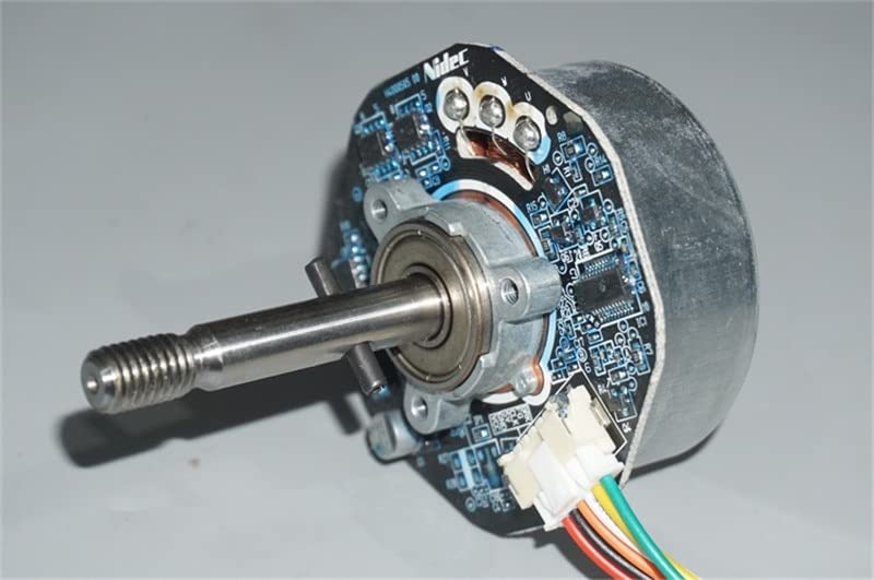
Figure 2: Wiring Diagram for Nidec 42F704M450 Motor. This diagram illustrates the connection points for power, CLK signal, and control lines. The red wire is typically positive (+), black is negative (-), and other wires are for control signals like 5V output, CLK (50-300Hz), and FG (Feedback Ground). The 'start stop' line connects to the negative pole to initiate operation.
- Power Input: Connect your regulated DC 12V-24V power supply to the designated positive (+) and negative (-) terminals.
- CLK Signal: The motor's speed is controlled by a CLK signal ranging from 50Hz to 300Hz. Connect your control signal source to the CLK input.
- Start/Stop: Connect the 'start stop' line to the negative pole to start the motor.
- 5V Output: A 5V output is available for external components if needed.
3.2 Mounting
The motor features mounting points for secure installation. Refer to the dimensions for proper integration into your system.
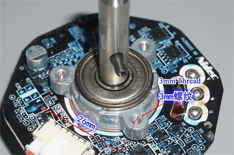
Figure 3: Motor Mounting Points. This image shows the underside of the motor, indicating the location of the 3mm threaded mounting holes and their spacing (26mm).
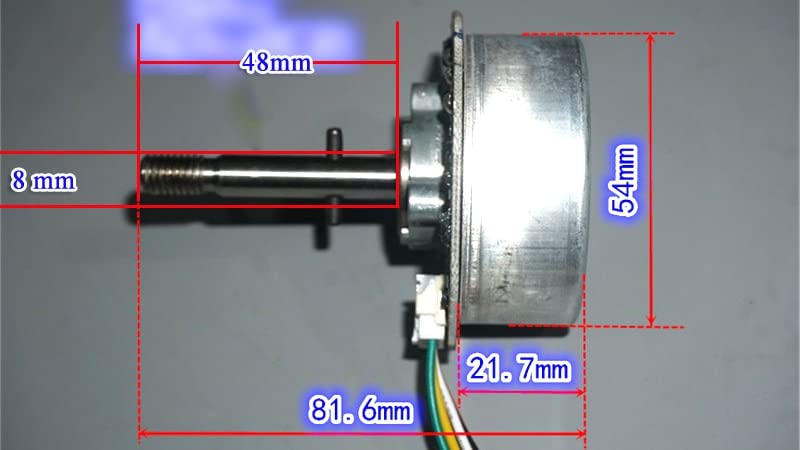
Figure 4: Motor Dimensions. This image provides key dimensions of the motor, including the 54mm external rotor diameter, 8mm shaft diameter, 48mm shaft length, and overall length of 81.6mm.
4. Operating Instructions
4.1 Powering On
After ensuring all wiring is correct and secure, apply power from your regulated 12V-24V DC source. The motor features a slow start function for smooth initial rotation.
4.2 Speed Control
The motor's speed is controlled by the frequency of the CLK signal. A CLK signal between 50Hz and 300Hz will regulate the motor speed. The maximum speed is 950 RPM, and any excessive speed commands will be limited by the integrated driver.
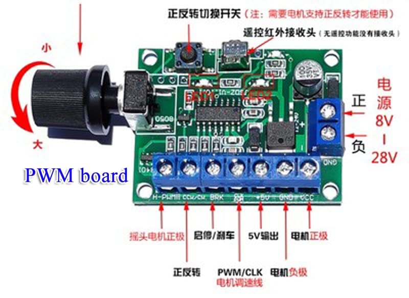
Figure 5: Example PWM Control Board. This image shows a generic PWM control board, which can be used to generate the CLK signal for speed regulation of the Nidec motor. Note the power input range (8V-28V) and control terminals.
4.3 Direction of Rotation
When viewed from the long shaft end, the motor operates in a clockwise direction.
5. Maintenance
The Nidec 42F704M450 motor is designed for low maintenance. Follow these general guidelines to ensure longevity:
- Keep the motor clean and free from dust and debris.
- Regularly inspect wiring connections for any signs of wear or looseness.
- Avoid exposing the motor to extreme temperatures or humidity.
6. Troubleshooting
If you encounter issues with your motor, consider the following:
- Motor Not Starting:
- Check power supply voltage (must be 12V-24V DC).
- Verify correct positive and negative polarity.
- Ensure the 'start stop' line is correctly connected to the negative pole.
- Confirm the CLK signal is present and within the 50-300Hz range.
- Incorrect Speed:
- Check the frequency of the CLK signal.
- Ensure the power supply is stable and providing adequate current.
- Motor Overheating:
- Ensure the motor is not overloaded.
- Verify adequate ventilation around the motor.
- Motor Burnout: This is typically caused by incorrect wiring, especially reversed polarity. Always double-check connections before applying power.
7. Specifications
| Feature | Specification |
|---|---|
| Model Number | 42F704M450 |
| Brand | Generic (Nidec) |
| Operating Voltage | DC 12V - 24V |
| Control Mode | CLK Signal (50-300Hz) |
| Max No-Load Speed (24V) | 950 RPM |
| No-Load Current (24V) | 0.07 A |
| Max No-Load Speed (12V) | 500 RPM |
| No-Load Current (12V) | 0.06 A |
| Rotor Type | External Rotor |
| Rotor Diameter | 54 mm |
| Bearings | Double Ball Bearings |
| Weight | Approximately 200 g |
| Origin | China Mainland |
8. Warranty and Support
Information regarding warranty coverage and customer support for this product is not available in the provided details. Please refer to your point of purchase or the manufacturer's official channels for specific warranty terms and support options.
