
SEAFRONT SEAFRONTqbks9m7dhv
SEAFRONT 1.1kW Variable Frequency Drive (VFD) User Manual
Model: SEAFRONTqbks9m7dhv
1. Introduction
This manual provides essential information for the safe and efficient operation of your SEAFRONT 1.1kW Variable Frequency Drive (VFD). Please read this manual thoroughly before installation, operation, or maintenance to ensure proper usage and prevent potential hazards. Keep this manual for future reference.
The SEAFRONT VFD is designed to control the speed of 3-phase motors, converting a single-phase input (176-264V) into a three-phase output (0-220V) with a frequency range of 0.1-400Hz. It features V/F control, vector control, and output torque control, along with an external LED digital display panel for easy monitoring and adjustment.

Figure 1: Front view of the SEAFRONT 1.1kW VFD, showing the LED display, control buttons (PROG, RUN, STOP, OK, UP, DOWN), and a rotary knob for frequency adjustment.
2. Safety Information
Always observe the following safety precautions to prevent personal injury or damage to the equipment:
- Installation and wiring must be performed by qualified personnel only.
- Ensure the power supply is disconnected before performing any wiring or maintenance.
- Do not touch the terminals while power is applied or shortly after power is removed, as residual voltage may be present.
- The VFD enclosure is made of flame-retardant PC material, providing good insulation. However, proper grounding is essential.
- Do not operate the VFD with damaged cables or if the enclosure is open.
- Protect the VFD from moisture, dust, direct sunlight, and corrosive gases.
3. Product Overview and Features
The SEAFRONT 1.1kW VFD is a compact and robust motor speed controller designed for various industrial applications. Key features include:
- Multiple Control Modes: Supports V/F control, vector control, and output torque control for versatile motor management.
- Durable Construction: Features a flame-retardant PC enclosure for good insulation and environmental protection.
- High Performance Coils: Utilizes copper core coils for strong resistance, stable performance, and high load capacity.
- Wide Frequency Range: Operates within a frequency range of 0.1-400Hz.
- External LED Display: Equipped with an external LED digital display panel for clear status indication and parameter adjustment.
- Compact Design: Small size with high torque output, suitable for various applications.
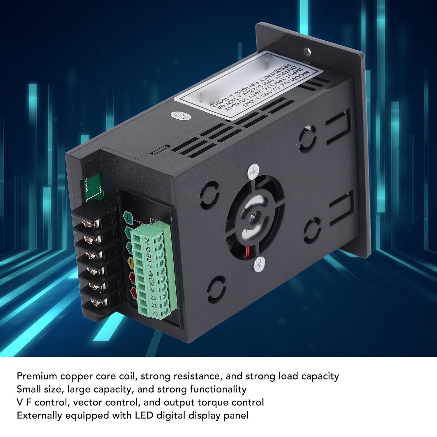
Figure 2: Internal components of the VFD, highlighting the premium copper core coils for stable performance and the integrated cooling fan.
4. Setup and Installation
4.1 Unpacking and Inspection
Upon receiving the VFD, carefully unpack it and inspect for any signs of damage during transit. Verify that all components are present according to the packing list (if provided). If any damage or missing parts are found, contact your supplier immediately.
4.2 Mounting
Mount the VFD in a vertical position on a flat, stable surface. Ensure adequate ventilation around the unit to prevent overheating. Maintain sufficient clearance from other equipment and walls for proper airflow. Avoid mounting in areas with excessive vibration, dust, or direct heat sources.
4.3 Wiring
All wiring must comply with local electrical codes and safety regulations. Ensure the main power supply is disconnected before proceeding with any wiring.
- Power Input (AC): Connect the single-phase 176-264V AC power supply to the "AC" terminals. Ensure correct polarity if applicable, though AC typically does not have strict polarity.
- Motor Output (U, V, W): Connect the three-phase motor leads to the "U", "V", and "W" output terminals.
- Ground (FG): Connect the frame ground (FG) terminal to a reliable earth ground. This is crucial for safety.
- Control Terminals (RS+, RS-, GND, V+, +5V, COM, X1, X2, X3, X4): These terminals are for external control signals, such as remote start/stop, speed reference (analog input V+), and digital inputs (X1-X4). Refer to the detailed wiring diagram for specific connections based on your application.

Figure 3: Wiring terminals on the VFD, including AC input, U/V/W motor output, FG ground, and control terminals.
5. Operating Instructions
5.1 Initial Power-Up
After completing all wiring and safety checks, apply power to the VFD. The LED display should illuminate, indicating the unit is powered on. The display will typically show the current frequency or a default parameter.
5.2 Basic Operation
- Start/Stop: Press the RUN button to start the motor and the STOP button to stop it.
- Frequency Adjustment: Use the rotary knob on the front panel to adjust the output frequency, which directly controls the motor speed. Turn clockwise to increase frequency, counter-clockwise to decrease.
- Parameter Navigation: Use the PROG button to enter the parameter setting mode. Use the UP and DOWN buttons to navigate through parameters. Press OK to select a parameter and confirm changes.
5.3 Advanced Control Settings
The VFD offers various programmable parameters for fine-tuning motor control. These include acceleration/deceleration times, maximum/minimum frequencies, V/F curve settings, and input/output terminal configurations. Refer to the detailed parameter list in the full technical manual for advanced programming.
Example Applications: The VFD is suitable for a wide range of equipment, including fans, water pumps, automated machine tools, and engraving machines.

Figure 4: Common application scenarios for the SEAFRONT VFD, demonstrating its versatility in industrial and automated settings.
6. Maintenance
Regular maintenance helps ensure the longevity and reliable operation of your VFD. Always disconnect power before performing any maintenance.
- Cleaning: Periodically clean the VFD's exterior and ventilation openings to prevent dust accumulation, which can hinder cooling. Use a soft, dry cloth. Do not use liquid cleaners.
- Fan Inspection: Check the cooling fan for proper operation and ensure it is free from obstructions. Replace the fan if it becomes noisy or stops working.
- Terminal Tightness: Periodically check all terminal connections for tightness. Loose connections can cause overheating and intermittent operation.
- Environmental Check: Ensure the operating environment remains within specified temperature and humidity ranges.
7. Troubleshooting
This section provides solutions to common issues. For problems not listed here or if issues persist, contact technical support.
| Problem | Possible Cause | Solution |
|---|---|---|
| VFD does not power on | No input power; incorrect wiring; blown fuse. | Check power supply; verify wiring connections; inspect fuses. |
| Motor does not start | Incorrect control signal; motor wiring error; VFD in fault state. | Check RUN command; verify motor connections (U, V, W); check VFD display for error codes. |
| Motor speed unstable | Improper V/F curve setting; motor load fluctuations; interference. | Adjust V/F parameters; ensure stable load; check for electromagnetic interference. |
| Overcurrent/Overload fault | Motor overloaded; acceleration time too short; short circuit in motor wiring. | Reduce motor load; increase acceleration time; check motor and wiring for shorts. |
8. Specifications
| Parameter | Value |
|---|---|
| Model Number | SEAFRONTqbks9m7dhv |
| Input Voltage | 1PH 176-264V |
| Output Voltage | 3PH 0-220V |
| Rated Power | 1.1kW |
| Rated Current | 6A |
| Frequency Range | 0.1-400Hz |
| Control Modes | V/F control, Vector control, Output torque control |
| Enclosure Material | Flame-retardant PC |
| Display | External LED Digital Display Panel |

Figure 5: Dimensional drawing of the VFD, indicating measurements for installation planning.
9. Warranty and Support
This product comes with a standard manufacturer's warranty. For specific warranty terms and conditions, please refer to the documentation provided with your purchase or contact your retailer. For technical support, troubleshooting assistance, or spare parts inquiries, please contact SEAFRONT customer service or your authorized distributor.
Note: Availability of spare parts information is currently unavailable. Please contact support for assistance.
Ask a question about this manual
Ask about setup, troubleshooting, compatibility, parts, safety, or missing instructions. Manuals+ will review the question and use this page’s manual context to help answer it.