
1. Introduction
This manual provides essential information for the proper installation, operation, and maintenance of your Bisida 12S 38.4V 20A Lifepo4 Battery Management System (BMS). This BMS is designed to protect 12-series 38.4V Lifepo4 battery packs, ensuring their longevity and safe operation. Please read this manual thoroughly before use.
2. Product Features
- Multiple Protection Functions: Includes overcharge protection, over-discharge protection, overcurrent protection, short-circuit protection, temperature protection, and downtime protection.
- Voltage Balance: Features passive balance to help maintain cell voltage consistency within the battery pack.
- Wide Operating Temperature Range: Supports charging and discharging in temperatures from -20°C to 70°C.
- Integrated NTC Temperature Control: Equipped with an NTC temperature control probe for accurate temperature monitoring.
- Common Port Design: Simplifies wiring for both charging and discharging.

Image: Diagram illustrating the ten types of protection functions integrated into the BMS, such as overcurrent, short circuit, overcharge, over discharge, temperature, moisture, dust, electrostatic, drop, and balanced protection.

Image: Close-up view of the NTC temperature control probe, indicating its role in temperature management for the battery system.
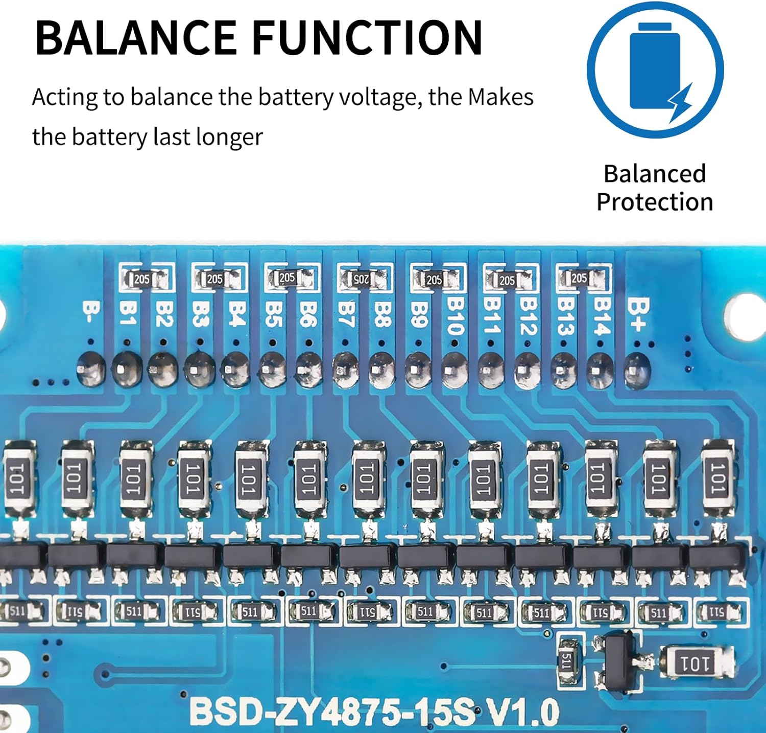
Image: Detailed view of the BMS board highlighting the balance function components and connection points for individual battery cells (B- to B+).
3. Installation and Wiring
Important Notice Before Installation:
Before installing the BMS protective board, it is crucial to ensure that the voltage, capacity, and internal resistance of all individual battery cells are matched. The voltage difference between cells should not exceed 0.05V, the internal resistance difference should not be more than 5mΩ, and the capacity difference should be less than 30mAh. Failure to meet these conditions may prevent the battery pack from charging correctly.
Wiring Method (Common Port):
- B- Connection: Connect B- to the negative terminal of the battery pack.
- C- Connection: Connect C- to both the charging negative and the output negative terminals.
- Positive Electrodes: All positive electrodes of the battery cells connect to the total positive pole of the battery pack.
- Balance Wires: Connect the balance wires sequentially, starting with the black wire to the first negative cell, and continuing in ascending order of voltage to B1, B2, etc., up to B+.
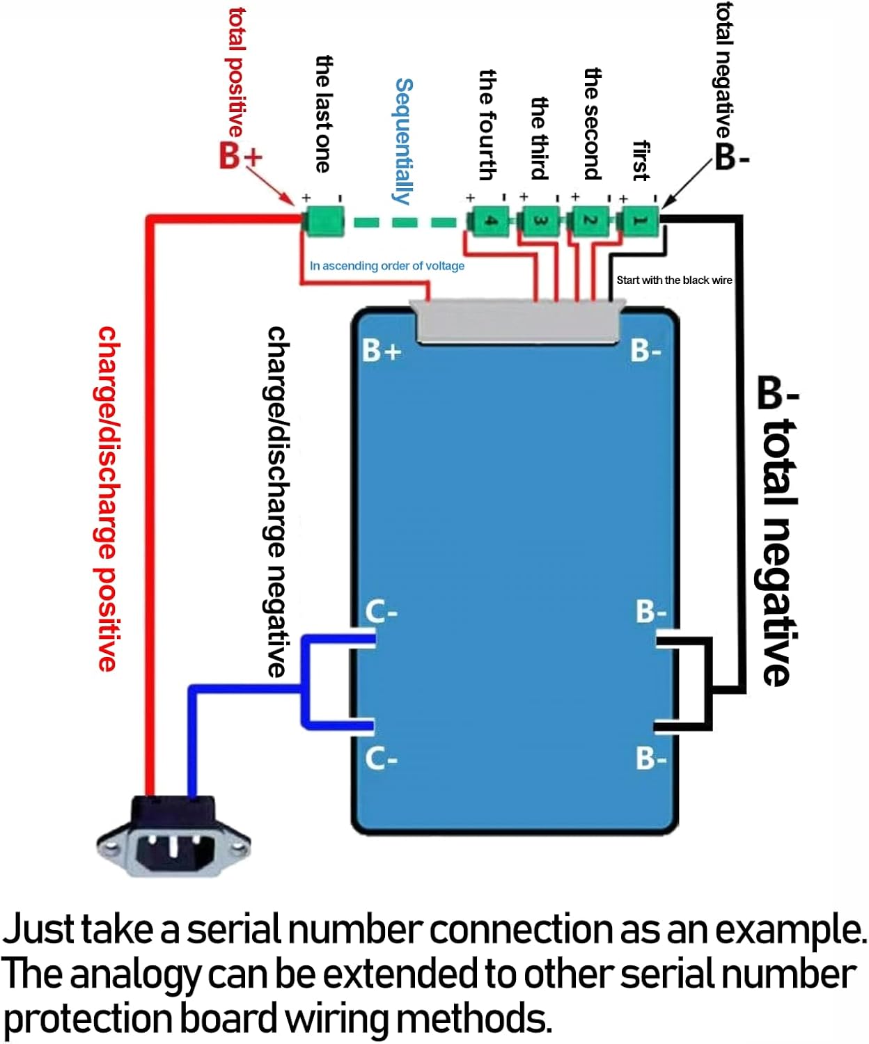
Image: A detailed wiring diagram illustrating the serial connection of a battery pack to the BMS, including connections for charge/discharge positive, charge/discharge negative, total negative (B-), and individual cell balance wires (B1, B2, etc., up to B+).
4. Operating Conditions
The Bisida BMS supports Lifepo4 battery charging and discharging within a cell voltage range of 2.3V to 3.65V (for 3.2V nominal cells). The operational temperature range is from -20°C to 70°C. Specific parameter details may vary with different voltages and currents; refer to the specifications table for precise values.
5. Specifications
The following table outlines the key specifications and protection parameters for the Bisida 12S 38.4V 20A Lifepo4 BMS.

Image: A table detailing Lifepo4 data and various protection parameters for the BMS, such as overcharge voltage, over-discharge voltage, short circuit delay time, temperature protection thresholds, and balance current.
| Parameter | Value |
|---|---|
| Brand | Bisida |
| Model Number | Bisida Lifepo4 BMS 12S 38.4V |
| Item Weight | 0.09 Kilograms |
| Output Voltage | 38.4 Volts |
| Input Voltage | 43.2 Volts |
| Current Rating | 20 Amps |
| Amperage | 20 Amps |
| UPC | 749755334496 |
6. Troubleshooting
- Battery Pack Not Charging: Verify that all individual battery cells are matched in voltage, capacity, and internal resistance as specified in the 'Important Notice Before Installation' section. An imbalance can prevent proper charging.
- BMS Not Functioning: Check all wiring connections according to the 'Wiring Method' section. Ensure B- is correctly connected to the battery pack negative and C- to both charging and output negatives.
- Unexpected Shutdowns: This could indicate activation of a protection function (e.g., overcharge, over-discharge, overcurrent, or temperature protection). Check battery cell voltages, current draw, and operating temperature against the specifications.
7. Safety Information
- Always handle battery packs and BMS boards with care.
- Ensure proper insulation to prevent short circuits.
- Do not attempt to modify the BMS board.
- Keep the BMS and battery pack away from moisture and extreme temperatures outside the specified operating range.
- If you are unsure about any installation steps, consult a qualified professional.