
1. Introduction
This manual provides essential information for the proper installation, operation, and maintenance of the Bisida 16S 60V 50A Li-ion PCB Protection Board (BMS). This BMS is designed to manage and protect 16-series lithium-ion battery packs, ensuring their longevity and safe operation in applications such as solar energy storage and balance cars.
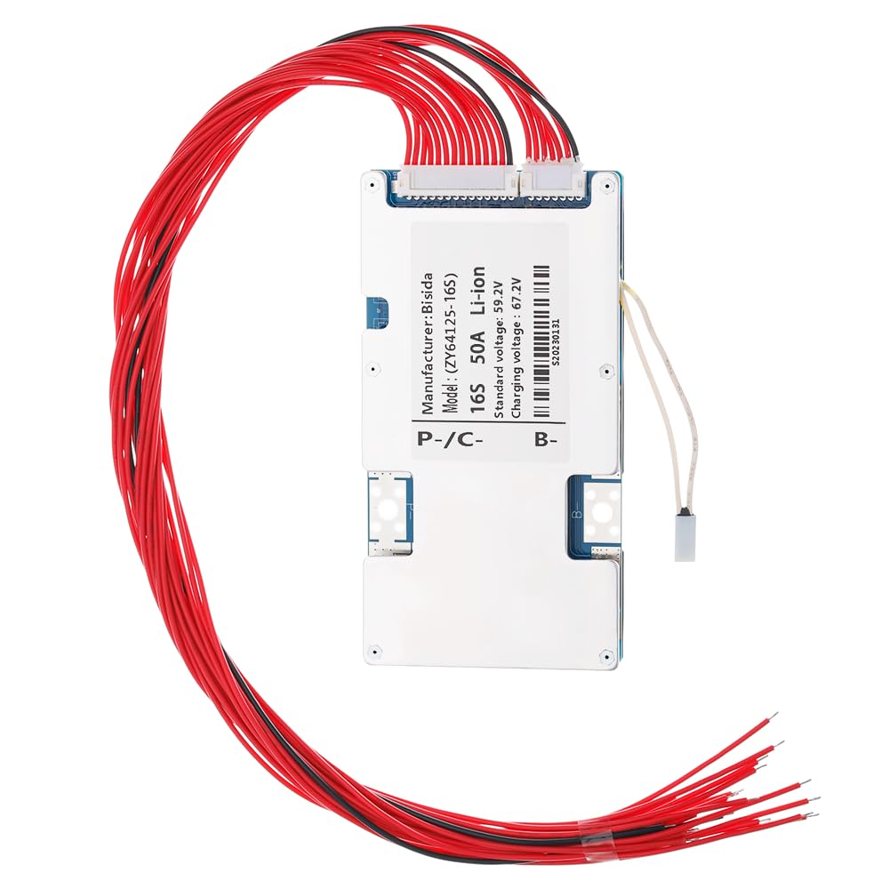
Figure 1: Bisida 16S 60V 50A Li-ion PCB Protection Board. A top-down view of the Bisida 16S 60V 50A Li-ion PCB Protection Board, showing its compact design and various components.
2. Key Features and Protections
The Bisida BMS incorporates a comprehensive set of protection functions to safeguard your battery pack:
- Overcharge Protection: Prevents cells from being charged beyond their safe voltage limit.
- Over-discharge Protection: Stops discharge when cell voltage drops below a safe minimum.
- Overcurrent Protection: Limits current flow to prevent damage from excessive loads.
- Short-circuit Protection: Immediately cuts off power in case of a short circuit.
- Temperature Protection: Monitors battery temperature and initiates protective measures if temperatures exceed safe operating limits (low and high).
- Disconnect Protection: Ensures safe operation in case of connection issues.
- Voltage Balance (Passive Balance): Helps equalize cell voltages within the pack, extending battery life.
- Moisture Protection: Designed to resist moisture ingress.
- Dust Protection: Designed to resist dust ingress.
- Electrostatic Protection: Shields against electrostatic discharge.
- Drop Protection: Enhanced durability against physical impact.

Figure 2: Integrated Protection Features. An infographic displaying icons and text for ten protection features: Overcurrent, Short circuit, Overcharge, Over discharge, Temperature, Disconnect, Voltage balance, Moisture, Dust, and Electrostatic protection.
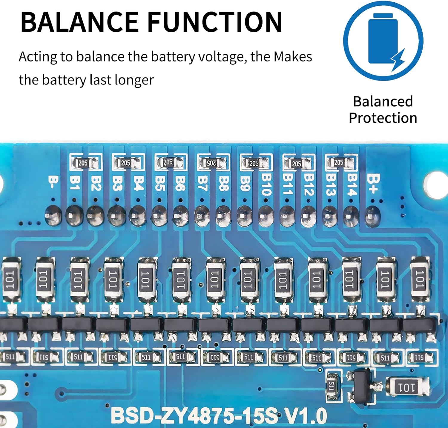
Figure 3: NTC Temperature Control Probe. A detailed image showing the NTC temperature control probe connected to the BMS, highlighting its role in temperature management.

Figure 4: Balance Function Components. A magnified view of the BMS circuit board, illustrating the components responsible for the balance function, which helps equalize cell voltages and extend battery life.
3. Setup and Installation
3.1 Pre-installation Notice
Before installing the BMS protective board, it is crucial to ensure that the voltage, capacity, and internal resistance of all individual battery cells are matched. The voltage difference between cells should not exceed 0.05V, the internal resistance difference should not be more than 5mΩ, and the capacity difference should be less than 30mAh. Failure to meet these conditions may prevent the battery pack from charging correctly or operating efficiently.
3.2 Wiring Method (Common Port)
The Bisida 16S 60V 50A BMS uses a common port for charging and discharging. Follow these steps for correct wiring:
- B- Connection: Connect the B- terminal of the BMS to the total negative terminal of the battery pack.
- C- Connection: Connect the C- terminal of the BMS to both the charging negative and the output negative terminals.
- Positive Connections: All positive electrodes from the battery cells should be connected to the total positive pole of the battery pack.
- Balance Wire Connection: Connect the balance wires sequentially from the first cell's negative terminal (B0) up to the last cell's positive terminal (B16), ensuring the black wire starts at B0 (total negative).

Figure 5: BMS Wiring Diagram. A schematic diagram showing the correct wiring connections for the BMS, including B- (total negative), B+ (total positive), C- (charge/discharge negative), and sequential cell connections. This diagram illustrates a serial connection example, which can be adapted for other serial number protection board wiring methods.
4. Operating Conditions
The Bisida BMS supports 3.7V lithium-ion battery charging and discharging within a voltage range of 2.65V to 4.25V per cell. It features low temperature protection down to -20°C and high temperature protection up to 70°C. Specific parameter details may vary with different voltages and currents; always refer to the detailed specifications for confirmation.
5. Specifications
Below are the technical specifications for the Bisida 16S 60V 50A Li-ion PCB Protection Board:
- Model Number: 16S 60V 50A
- Battery Cell Composition: Lithium Ion
- Recommended Uses: Electric Motorcycle, Solar Energy Storage, Balance Car Lithium-ion Battery Pack
- Package Dimensions: 6.85 x 3.7 x 2.24 inches
- Item Weight: 6.4 ounces
- Operating Temperature Range: -20°C to 70°C

Figure 6: Li-ion Data and Protection Parameters. A table detailing various Li-ion battery parameters and protection thresholds, including overcharge voltage, over-discharge voltage, overcurrent delay times, short circuit conditions, and operating temperature range. Note: Test environment is 25°C, relative humidity is less than or equal to 90%.
6. Maintenance
To ensure optimal performance and longevity of your Bisida BMS and battery pack, consider the following maintenance guidelines:
- Regular Inspection: Periodically check all wiring connections for tightness and signs of corrosion or damage.
- Cleanliness: Keep the BMS and battery pack free from dust and debris. Use a soft, dry cloth for cleaning.
- Environmental Control: Operate and store the battery pack within the specified temperature and humidity ranges to prevent premature degradation.
- Avoid Physical Shock: Protect the BMS from strong impacts or vibrations.
7. Troubleshooting
If you encounter issues with your Bisida BMS, consider the following basic troubleshooting steps:
- No Power Output: Verify all wiring connections are secure and correct according to the diagram. Check individual cell voltages to ensure none are critically low or high.
- Charging Issues: Confirm that the charger is functioning correctly and that the battery cells meet the pre-installation matching criteria (voltage, capacity, internal resistance).
- Overheating: Ensure adequate ventilation around the BMS and battery pack. Check for excessive current draw.
- Unbalanced Cells: Allow the BMS to perform its passive balancing function over time. If severe imbalance persists, re-check individual cell health.
For persistent issues, consult a qualified technician or contact Bisida customer support.
8. Warranty and Support
Specific warranty details for the Bisida 16S 60V 50A Li-ion PCB Protection Board are not provided in this document. Please refer to your purchase documentation or contact the retailer/manufacturer directly for warranty information and technical support.
For further assistance, you may contact Bisida customer service through their official channels.