
Introduction
The SignalBrick Cell Signal Booster is designed to enhance cellular signal strength within your home or multi-room environment. This device improves voice, text, and data signals for 2G, 3G, 4G LTE, and 5G-ready networks, covering an area of up to 8000 sq. ft. It features a smart LCD display for real-time signal monitoring and is compatible with major Canadian carriers including Fido, Bell, Telus, Rogers, Sasktel, and MTS.
Package Contents
Verify that all the following components are included in your package:
- 1 x Signal Booster Unit
- 1 x Outdoor Antenna
- 1 x Power Supply & Splitter
- 2 x Indoor Panel Antennas
- 3 x 30 ft Coaxial Cables (RG6)
- 1 x 15 ft Coaxial Cable (RG6)
- Mounting Accessories

Product Overview
The SignalBrick Cell Signal Booster system consists of three main parts working together to improve your cellular reception:
- Outdoor Antenna: Captures existing cellular signals from the nearest cell tower and sends them to the booster.
- Signal Booster: Amplifies the weak signals received from the outdoor antenna and prepares them for distribution indoors.
- Indoor Antennas: Broadcast the amplified signals throughout your desired indoor areas, providing improved coverage.

Setup Guide
1. Pre-Installation Check
Before installation, identify the location with the strongest outdoor cellular signal. This is typically on the roof or an exterior wall of your building. Use your mobile phone to check signal bars or a signal strength app to find the optimal spot.
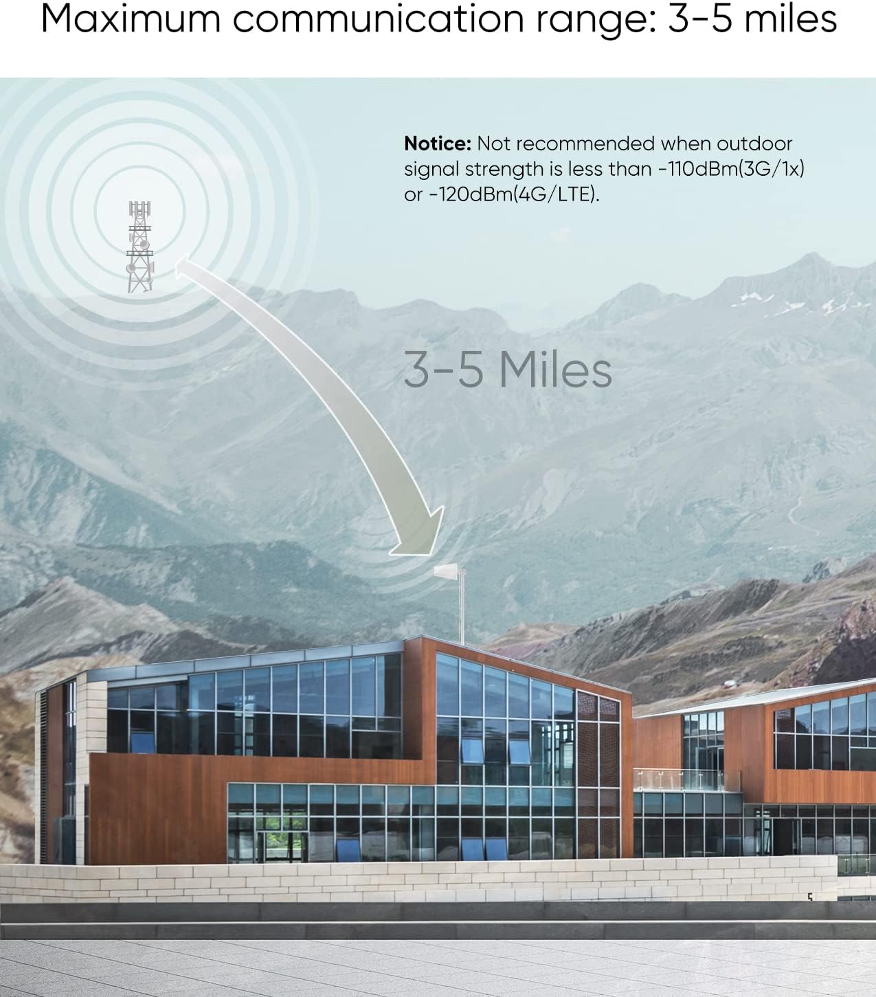
2. Outdoor Antenna Placement
- Mount the outdoor antenna in the location identified with the strongest signal.
- Ensure the outdoor antenna is pointed towards the nearest cell tower.
- Maintain a minimum vertical separation of 30 feet (approximately 9 meters) between the outdoor and indoor antennas to prevent signal oscillation.

3. Indoor Antenna Placement
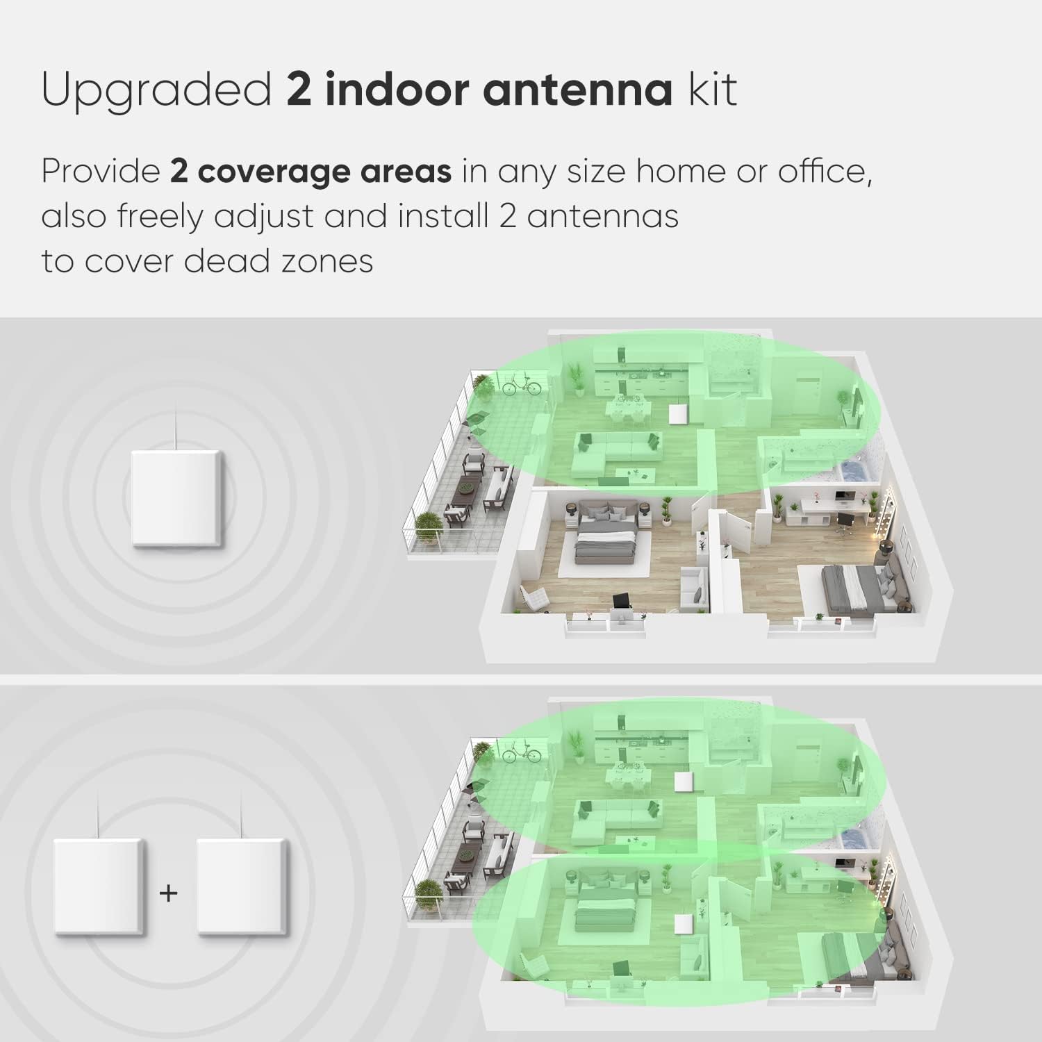
- Install the two indoor panel antennas in the areas where you need improved signal coverage.
- For multi-room or multi-floor coverage, strategically place the antennas to cover dead zones.
- The system is designed to provide coverage up to 8000 sq. ft. with two indoor antennas.

4. Connecting Components
- Connect the coaxial cable from the outdoor antenna to the port labeled "Outdoor" on the Signal Booster unit.
- Connect the splitter to the port labeled "Indoor" on the Signal Booster unit.
- Connect the two indoor antennas to the splitter using the provided coaxial cables.
- Connect the power supply to the Signal Booster unit, then plug the power adapter into an electrical outlet.

5. Power On
Once all connections are secure, plug in the power adapter. The booster will power on, and the LCD display will activate, showing signal status.
Operating Instructions
1. Smart LCD Display
The integrated Smart LCD Display provides real-time information about the booster's operation. It clearly shows the indoor signal strength, updating every 1.5 seconds, and the operational status of each frequency band. This allows you to easily monitor signal conditions without needing an external app.
2. Signal Monitoring
Regularly check the LCD display to ensure optimal signal reception and transmission. If signal strength is not satisfactory, consider adjusting the direction of the outdoor antenna or the placement of the indoor antennas.
3. Multi-User and Multi-Device Support
The SignalBrick booster is designed to support multiple users and devices simultaneously. It automatically adjusts system gain and power levels to provide optimal results for your 5G phones, tablets, data cards, and laptops, ensuring stable call quality and network connection for everyone.

Maintenance
To ensure the longevity and optimal performance of your SignalBrick Cell Signal Booster, follow these maintenance guidelines:
- General Care: Keep the booster unit clean and free from dust. Use a soft, dry cloth for cleaning. Avoid using liquid cleaners or abrasive materials.
- Heat Dissipation: The booster features an aluminum housing with an integrated radiator for efficient heat dissipation. Ensure that the ventilation areas are not obstructed to maintain stable performance and prolong the life of internal components.
- Environmental Protection: The fully enclosed metal casing is designed to limit electromagnetic radiation inside the device, preventing radiation and interference to the surrounding environment. No specific user maintenance is required for this feature.
Troubleshooting
If you encounter issues with your SignalBrick Cell Signal Booster, refer to the following common troubleshooting steps:
- No Signal or Weak Signal:
- Verify that all coaxial cable connections are secure and properly tightened.
- Ensure there is a minimum vertical separation of 30 feet (9 meters) between the outdoor and indoor antennas. Insufficient separation can lead to oscillation and reduced performance.
- Adjust the direction of the outdoor antenna. Slowly rotate it to find the strongest signal from the nearest cell tower.
- Check the LCD display for any error indicators or unusually low signal readings.
- Alarm Lights On:
- If alarm lights are illuminated, it typically indicates oscillation (feedback loop) or an issue with signal isolation.
- Increase the physical separation between the outdoor and indoor antennas.
- Ensure the outdoor antenna is not pointing directly towards the indoor antennas.
- Interference with Other Wireless Devices:
- In some cases, the booster may cause minor interference with other wireless devices, such as smart hubs or Wi-Fi routers, especially if they operate on similar frequencies or are in close proximity.
- If interference occurs, try increasing the distance between the booster/antennas and the affected devices. You may also consider temporarily powering off the booster when using the affected devices, or contact customer support for further assistance.
This cell phone booster is ISED (Innovation, Science and Economic Development Canada) approved. The IC Certification number is 10198A-SR75702002, and the Hardware Version Identification Number (HVIN) is SR75702002B. Users are required to register this device with their wireless provider and obtain their consent for operation.

Specifications
| Brand | SignalBrick |
| Model | B0CC234X3X |
| Coverage Area | Up to 8000 sq. ft. |
| Data Transfer Rate | 40 Megabits Per Second |
| Frequency Bands Supported | Band 12/17 (698-716MHz), Band 13 (777-787MHz), Band 5 (824-849MHz), Band 25/2 (1850-1915MHz), Band 4/66 (1710-1755MHz) |
| Compatible Carriers | Fido, Bell, Telus, Rogers, Sasktel, MTS (2G/3G/4G LTE, 5G ready) |
| Maximum Gain | 70 dB |
| Power Supply | DC 12V/1.5A |
| Parcel Dimensions | 36.9 x 23.5 x 18.7 cm |
| Parcel Weight | 3.97 kg |
| IC Certification Number | 10198A-SR75702002 |
| HVIN | SR75702002B |
Warranty and Support
The SignalBrick Cell Signal Booster comes with a 3-year warranty from the date of purchase, covering defects in materials and workmanship. For technical assistance, troubleshooting, or to make a warranty claim, please contact SignalBrick customer support. Refer to the manufacturer's contact information provided with your product or visit the official SignalBrick website for support details.
