
1. Introduction
The Bisida 10S 36V 25A Li-ion PCB Protection Board (BMS) is designed to manage and protect 10-series 36V lithium-ion battery packs. It ensures the safe and efficient operation of your battery by monitoring various parameters and providing multiple protection functions. This manual provides essential information for the proper installation, operation, and maintenance of your BMS.
2. Key Features
- Comprehensive Protection: Includes overcharge, over-discharge, overcurrent, short-circuit, temperature, disconnect, and voltage balance protection.
- Temperature Control: Features an NTC temperature control probe for effective thermal management.
- Passive Balance Function: Helps to balance individual cell voltages, extending battery pack lifespan.
- Automotive Grade Chip: Utilizes high-quality integrated circuits for stable performance, lower temperature operation, and reduced power consumption.
- Anti-Surge Design: Incorporates TVS for enhanced durability and reliability.

Figure 2.1: Integrated solution with ten types of protection.
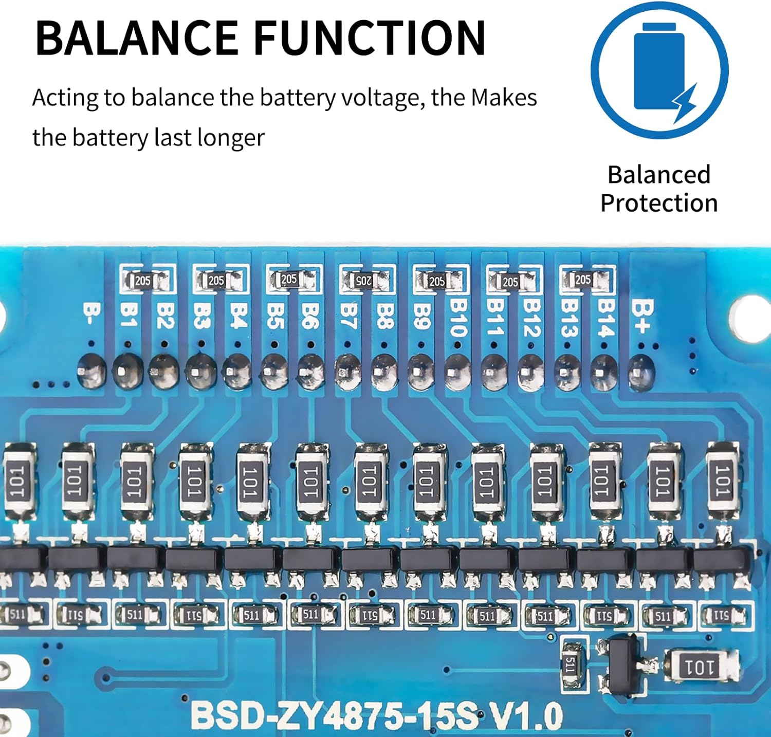
Figure 2.2: NTC temperature control probe for precise temperature monitoring.

Figure 2.3: Balance function components on the PCB.

Figure 2.4: Automotive Grade Chip for reliable performance.

Figure 2.5: Anti-Surge Design with TVS protection.
3. Setup and Wiring
3.1 Pre-installation Notice
Before installing the BMS protective board, it is crucial to ensure that the battery cells within the pack are matched in terms of voltage, capacity, and internal resistance. Specifically:
- The voltage difference between individual battery cells should not exceed 0.05V.
- The difference in internal resistance between cells should not be more than 5mΩ.
- The capacity difference between cells should be less than 30mAh.
Failure to meet these matching requirements may prevent the battery pack from charging correctly or lead to unbalanced operation.
3.2 Wiring Method (Split Ports)
For BMS models with split ports, follow these connection instructions:
- B- Connection: Connect B- to the negative terminal of the battery pack.
- C- Connection: Connect C- to the negative terminal of the charging input.
- P- Connection: Connect P- to the negative terminal of the output load.
- All positive electrodes (B+, C+, P+) are connected to the total positive pole of the battery pack.
Ensure that the balance wires are welded in order of increasing voltage, starting from B- (the main battery negative) and progressing through B1, B2, B3, up to B+ (the main battery positive).

Figure 3.1: Typical wiring diagram for the Bisida 10S BMS.
4. Operating Conditions
4.1 Temperature Range
The Bisida BMS supports 3.7V lithium-ion battery charging and discharging within specific voltage and temperature zones:
- Charging/Discharging Voltage Range: 2.65V to 4.25V per cell.
- Low Temperature Protection: Down to -20°C.
- High Temperature Protection: Up to 70°C.
Note that specific parameter details may vary with different voltages and currents. Always confirm the exact operating parameters for your specific application.
5. Maintenance
To ensure the longevity and optimal performance of your battery pack and BMS:
- Regularly inspect all wiring connections for tightness and corrosion.
- Avoid operating the battery pack outside the specified temperature range.
- The integrated balance function helps maintain cell voltage consistency, but periodic checks of individual cell voltages are recommended for critical applications.
- Keep the BMS clean and free from dust and moisture to prevent damage.
6. Troubleshooting
6.1 Battery Pack Not Charging
If your battery pack fails to charge after installing the BMS, consider the following:
- Cell Matching: Re-verify that all individual battery cells meet the pre-installation requirements for voltage, capacity, and internal resistance (voltage difference < 0.05V, internal resistance difference < 5mΩ, capacity difference < 30mAh). Significant discrepancies can prevent charging.
- Wiring: Double-check all wiring connections, especially the balance wires and the B-, C-, P- connections, against the provided wiring diagram. Ensure no wires are loose or incorrectly connected.
- Charger Compatibility: Confirm that your charger is compatible with a 10S 36V lithium-ion battery pack and is functioning correctly.
6.2 Other Issues
- No Output Power: Check for short-circuit protection activation or over-discharge protection. Ensure the battery pack voltage is above the minimum operating threshold.
- Overheating: Ensure adequate ventilation around the BMS and battery pack. Verify that the operating current does not exceed the BMS's rated capacity.
7. Specifications
| Specification | Detail |
|---|---|
| Brand | Bisida |
| Model Number | 10S 36V 25A |
| Voltage | 36 Volts |
| Amperage | 25 Amps |
| Battery Cell Composition | Lithium Ion |
| Reusability | Rechargeable |
| UPC | 749755110359 |
8. Warranty
This Bisida BMS product comes with a 1-Year Warranty from the date of purchase. The warranty covers defects in materials and workmanship under normal use. Please retain your proof of purchase for warranty claims.
9. Support
For technical assistance, troubleshooting, or warranty inquiries, please contact Bisida customer support through the retailer where the product was purchased or refer to the official Bisida website for contact information.