
Introduction
This manual provides essential information for the safe and effective installation and operation of your Bisida 10S 36V 15A Li-ion PCB Protection Board. This board is designed to manage and protect 10-series (10S) 36V lithium-ion battery packs with a continuous discharge current of up to 15A. It ensures the longevity and safety of your battery by preventing common issues such as overcharge, over-discharge, and short circuits.
Safety Precautions
Please read and understand all safety instructions before installation and use. Failure to follow these instructions may result in electric shock, fire, or other hazards.
- Installation should only be performed by qualified personnel with experience in battery systems.
- Ensure the battery pack voltage and current ratings are compatible with this BMS (10S 36V 15A).
- Avoid short-circuiting the BMS terminals or battery pack.
- Do not expose the BMS to water, excessive moisture, or extreme temperatures outside its operating range.
- Always wear appropriate personal protective equipment (PPE) during installation.
- Pre-Installation Notice: Before installing the BMS protective board, it is critical to match the voltage, capacity, and internal resistance of individual battery cells. The voltage difference between cells should not exceed 0.05V, the internal resistance difference should not exceed 5mΩ, and the capacity difference should be less than 30mAh. Failure to meet these conditions may prevent the battery pack from charging or balancing correctly.
Product Features
The Bisida BMS offers comprehensive protection and management for your lithium-ion battery pack, ensuring its safety and extending its lifespan.
- Multiple Protection Functions: Includes overcharge protection, over-discharge protection, overcurrent protection, short-circuit protection, and temperature protection.
- Disconnect Protection: Safeguards against issues arising from improper connections.
- Voltage Balance (Passive Balance): Helps maintain equal voltage across all battery cells, improving pack performance and longevity.
- NTC Temperature Control: Features a new generation NTC temperature control probe for accurate temperature monitoring.
- Automotive Grade Chip: Utilizes a small, integrated chip designed for lower temperature operation and reduced power consumption.
- Anti-Surge Design (TVS): Incorporates TVS for enhanced durability and reliability.

Figure 1: Integrated solution offering ten kinds of protection for the battery management system.

Figure 2: NTC temperature control probe for precise temperature monitoring.
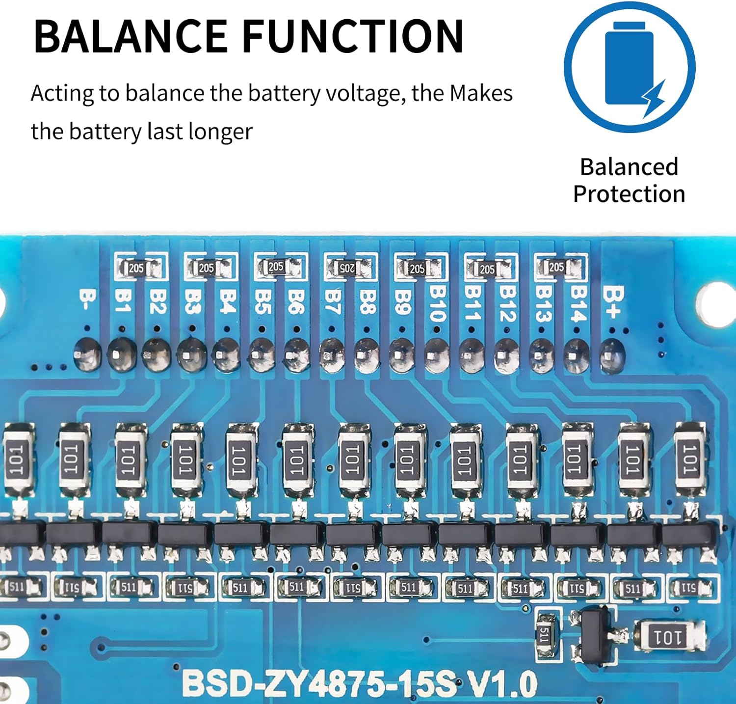
Figure 3: Balance function circuitry on the BMS board, ensuring balanced battery cell voltage.

Figure 4: Automotive grade chip for reliable and efficient performance.

Figure 5: Anti-surge design with TVS for enhanced protection.
Technical Specifications
| Specification | Detail |
|---|---|
| Model Number | 10S 36V 15A |
| Brand | Bisida |
| Nominal Voltage | 36 Volts |
| Continuous Discharge Current | 15 Amps |
| Battery Cell Type | Lithium Ion |
| Operating Temperature Range | -20°C to 70°C |
| UPC | 749755110335 |
| Recommended Use | Bicycle, e-Bike battery packs |
Installation Guide
Proper installation is critical for the safe and effective operation of the BMS. Ensure all connections are secure and correctly oriented.
Wiring Method (Split Ports)
The wiring methods for Split Ports of the BMS are as follows. Refer to the wiring diagram for visual guidance:
- B- Connection: Connect to the negative terminal of the battery pack.
- C- Connection: Connect to the negative terminal of the charging input.
- P- Connection: Connect to the negative terminal of the output (load).
- Positive Connections: All positive electrodes from the battery cells and the main positive output/charge connection should be connected to the total positive pole of the battery pack.
- Balance Wires: Connect the balance wires to each cell in increasing order of voltage, starting from B- (0V) up to B+ (total positive voltage).

Figure 6: Wiring diagram for the Bisida 10S 36V 15A BMS. Ensure connections are made in order of increasing voltage (B-, B1, B2, B3...B+).
Operation
Once correctly installed and connected, the Bisida BMS operates automatically to protect your battery pack. It continuously monitors cell voltages, total pack voltage, current flow, and temperature to ensure safe charging and discharging within the specified parameters.
Temperature Range
The BMS supports lithium-ion battery charging and discharging within an operating temperature range of -20°C to 70°C. Operation outside this range may trigger temperature protection or damage the battery pack.
Maintenance
To ensure optimal performance and longevity of your Bisida BMS and battery pack, follow these maintenance guidelines:
- Keep the BMS clean and free from dust, dirt, and moisture.
- Avoid physical impact or damage to the BMS board and its components.
- Ensure proper ventilation around the battery pack and BMS to prevent heat buildup.
- Periodically inspect all wiring connections for tightness and signs of corrosion.
- Do not attempt to repair or modify the BMS yourself. Refer to qualified technicians for service.
Troubleshooting
If you encounter issues with your Bisida BMS, refer to the following troubleshooting steps:
Battery Pack Not Charging
- Verify that all individual battery cells are matched in voltage, capacity, and internal resistance as specified in the "Pre-Installation Notice" under Safety Precautions.
- Check all wiring connections (B-, C-, P-, and positive connections) for correctness, secure contact, and absence of damage.
- Ensure the charger is functioning correctly and is compatible with the battery pack's voltage and current requirements.
BMS Overheating
- Check for excessive current draw during discharge or charge, which may exceed the BMS's rated 15A continuous current.
- Ensure adequate ventilation around the BMS and battery pack. Remove any obstructions to airflow.
- Verify that the ambient temperature is within the specified operating range (-20°C to 70°C).
Unexpected Shutdown
- An unexpected shutdown often indicates that a protection function has been triggered (e.g., over-discharge, overcurrent, short-circuit). Identify and resolve the underlying issue causing the protection.
- Check for loose connections or damaged wires that could lead to intermittent contact.
Warranty Information
The Bisida 10S 36V 15A Li-ion PCB Protection Board comes with a 1-year warranty from the date of purchase. This warranty covers manufacturing defects under normal use conditions. Please retain your proof of purchase for any warranty claims. The warranty does not cover damage caused by improper installation, misuse, unauthorized modification, or external factors.
Customer Support
For technical assistance, installation guidance, or any other inquiries regarding your Bisida 10S 36V 15A Li-ion PCB Protection Board, please contact Bisida customer support through the retailer or platform where the product was purchased. Provide your product model number and purchase details for efficient service.