
Safety Information
Please read and understand all safety information before operating this multimeter. Failure to follow these instructions may result in electric shock, fire, or personal injury. Keep this manual for future reference.
- Always ensure the multimeter is in good working condition before use.
- Do not apply voltage or current that exceeds the maximum specified limits for the multimeter.
- Use caution when working with voltages above 30V AC RMS, 42V peak, or 60V DC. These voltages pose a shock hazard.
- Ensure test leads are properly connected and in good condition. Replace damaged leads immediately.
- Do not operate the multimeter in explosive gas, vapor, or dusty environments.
- Always disconnect power to the circuit under test before measuring resistance, capacitance, or continuity.
- Do not attempt to repair or modify the multimeter. Refer servicing to qualified personnel.
Product Overview
The BSIDE A2X is a compact, rechargeable digital multimeter designed for various electrical measurements. It features a color LCD display, smart mode for automatic measurement, and a built-in flashlight for convenience.
Key Features:
- Smart Mode: Automatically detects and measures AC/DC voltage, resistance, and continuity.
- Automatic Amp Test Activation: Automatically switches to AC/DC ampere test mode when test leads are plugged into the amp port.
- Color LCD Display: Enhances readability in various lighting conditions.
- Rechargeable Battery: Integrated rechargeable Li-ion battery with USB charging.
- VFC Function: Measures AC voltage with variable frequency drives for accurate readings.
- Additional Functions: Capacitance, Diode, Frequency, V-Alert (Non-Contact Voltage), Live Wire Check, Environmental Temperature.
- Built-in Flashlight: For improved visibility in dark environments.
Setup
1. Charging the Multimeter
The BSIDE A2X multimeter comes with a built-in rechargeable Li-ion battery. Before first use, fully charge the device.
- Connect the provided charging cable to the multimeter's charging port.
- Connect the other end of the charging cable to a standard USB power adapter (not included) or a computer's USB port.
- The charging indicator will illuminate during charging and turn off when fully charged.

Image: The multimeter being charged via a USB cable, highlighting its rechargeable battery.
2. Connecting Test Leads
Properly connect the test leads to the multimeter before taking any measurements.
- Insert the red test lead into the "V/Ω/mA" input jack.
- Insert the black test lead into the "COM" (common) input jack.

Image: The BSIDE A2X multimeter with its accessories, including test leads, charging cable, and carrying case.
Operating Instructions
The BSIDE A2X features a smart mode for automatic detection of common measurements, as well as manual selection for specific functions.

Image: The multimeter's color LCD display showing various measurement functions and auto mode selection.
1. Power On/Off
Press and hold the power button (⏻) to turn the multimeter on or off.
2. Smart Mode (AUTO)
In Smart Mode, the multimeter automatically identifies and measures AC/DC voltage, resistance, and continuity. This is the default mode upon power-on.

Image: The multimeter's display highlighting the auto mode selection capability for various measurements.
3. Manual Function Selection
Press the "AUTO SEL" button to cycle through different measurement functions manually. The selected function will be indicated on the display.
- Voltage Measurement (AC/DC): Connect test leads in parallel to the circuit. Select AC or DC voltage mode if not in Smart Mode.
- Current Measurement (AC/DC): To measure current, plug the red test lead into the "mA" input jack. The multimeter will automatically activate the current test function. Connect the multimeter in series with the circuit. Caution: Do not measure current on circuits with voltage exceeding 600V.

Image: The multimeter demonstrating automatic amp test activation when leads are connected for current measurement.
- Resistance Measurement (Ω): Ensure the circuit is de-energized. Connect test leads across the component.
- Capacitance Measurement: Ensure the capacitor is discharged before testing. Connect test leads across the capacitor terminals.
- Diode Test: Ensure the circuit is de-energized. Connect the red lead to the anode and the black lead to the cathode.
- Continuity Test: Ensure the circuit is de-energized. Connect test leads across the circuit path. A beeper sounds if resistance is less than 50Ω.
- Frequency Measurement (Hz): Connect test leads to the signal source.
- VFC Function: For measuring AC voltage with variable frequency drives. Select VFC mode manually.
- V-Alert (NCV - Non-Contact Voltage): Hold the top of the multimeter near a live conductor. The device will indicate the presence of AC voltage without direct contact.
- Live Wire Check: Use the red test lead to touch the suspected live wire. The display will indicate "LIVE" if voltage is detected.
- Environmental Temperature: The multimeter can display the ambient temperature.
4. Flashlight
Press the flashlight button to turn the built-in LED flashlight on or off. This is useful for working in dimly lit areas.
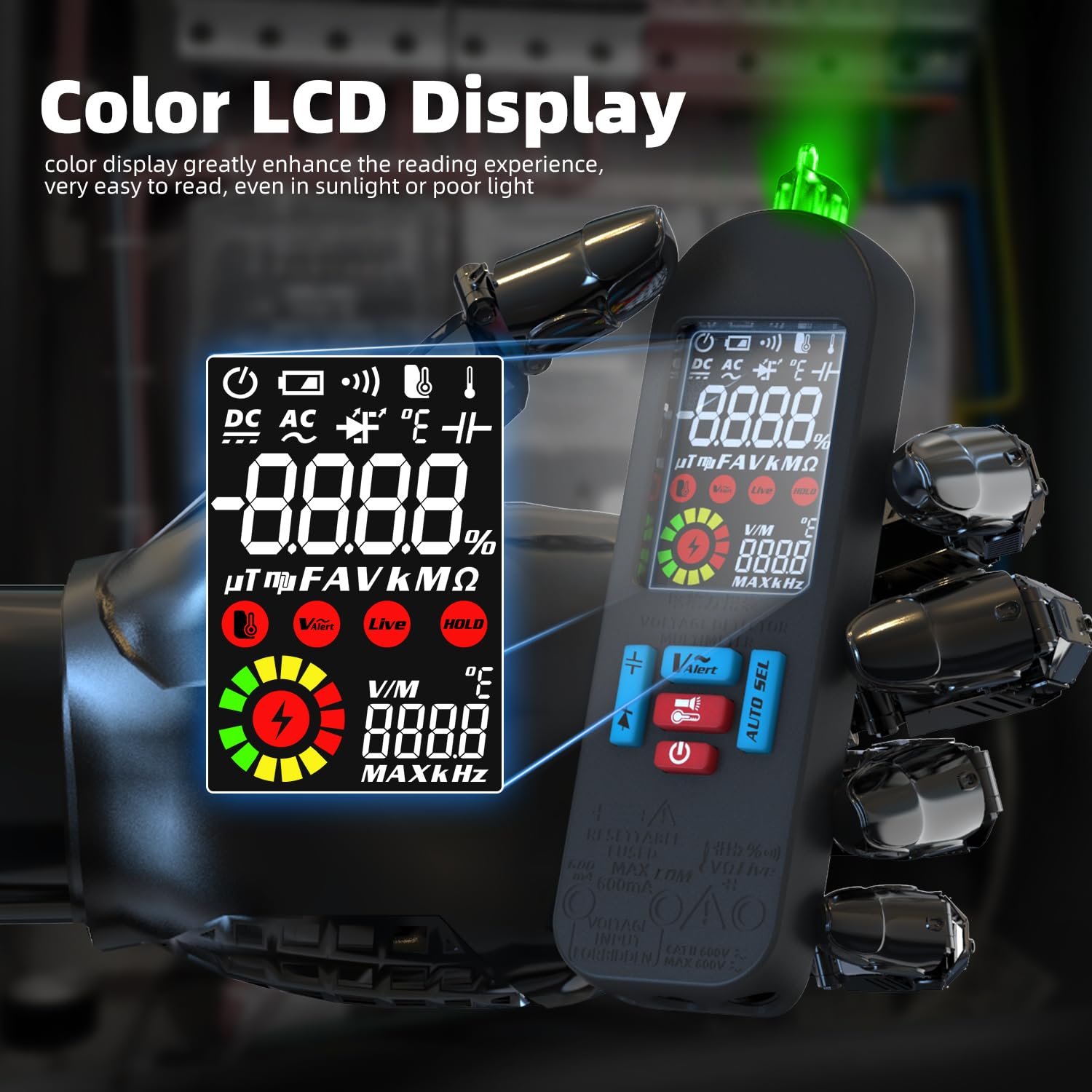
Image: The multimeter with its bright LED flashlight active, useful for testing in low-light conditions.
Maintenance
1. Cleaning
Wipe the multimeter casing with a damp cloth and mild detergent. Do not use abrasives or solvents. Ensure the device is powered off and disconnected from any circuits before cleaning.
2. Battery Care
The built-in Li-ion battery is rechargeable. Recharge the multimeter when the low battery indicator appears on the display. For long-term storage, charge the battery to approximately 50% every three months to prolong its lifespan.
3. Test Lead Inspection
Regularly inspect test leads for any signs of damage, such as cracked insulation or exposed metal. Replace damaged leads immediately to prevent electric shock hazards.
Troubleshooting
| Problem | Possible Cause | Solution |
|---|---|---|
| Multimeter does not power on. | Low or depleted battery. | Charge the multimeter using the provided USB cable. |
| Inaccurate readings. | Incorrect function selected; poor test lead connection; external interference. | Ensure correct function is selected (or use Smart Mode). Check test lead connections. Move away from strong electromagnetic fields. |
| No continuity beep. | Resistance is above 50Ω; circuit is not de-energized. | Verify the circuit is de-energized. Check the resistance value on the display. |
| Display shows "OL" (Overload). | Measurement exceeds the multimeter's range. | Ensure the measurement is within the specified range for the selected function. Disconnect immediately if measuring voltage/current beyond limits. |
Specifications
| Parameter | Range / Value |
|---|---|
| MAX Display | 6000 counts |
| DC Voltage | 0-620V (DC Mode) / 0.8-620V (Auto Mode) ±(0.8%+3) |
| AC Voltage | 60mV-620V (AC Mode) / 0.8V-620V ±(1.2%+5) |
| VFC AC Voltage | 10V-620V ±(4%+3) |
| DC Current | 1-610mA ±(1.5%+3) |
| AC Current | 1-610mA (40-1000Hz) ±(1.5%+3) |
| Resistance | 0-6MΩ ±(1.2%+3); 6MΩ-60MΩ ±(2.0%+10) |
| Capacitance | 0.5µF-6mF ±(3.5%+8); 6mF-60mF ±(4.5%+10) |
| Frequency | 0-999.9K Hz (900mVrms-20Vrms) ±(2.0%+10) |
| V-Alert (NCV) | Yes |
| Live Wire Check | Yes |
| Continuity Beeper | Sounds if resistance < 50Ω |
| Diode Test | Measures diodes within 3V |
| Environment Temperature | 0-50℃ ±2.0℃ |
| Power | 3.7V (built-in, rechargeable) |
| Size | 146 x 44 x 25.2 mm |
| Weight | 76g |
Warranty and Support
For warranty information or technical support, please refer to the documentation included with your purchase or contact the manufacturer directly. Keep your proof of purchase for warranty claims.


