
1. Introduction
This manual provides detailed instructions for the assembly, operation, and maintenance of your Qiilu 6DOF Robotic Arm Kit. Designed for educational, industrial, and DIY projects, this mechanical arm offers six degrees of freedom, allowing for versatile movement and gripping capabilities. Please read this manual thoroughly before beginning assembly or operation to ensure proper function and longevity of your robotic arm.
2. Product Overview
2.1. Key Features
- 6 Degrees of Freedom (6DOF): Enables complex movements including front, rear, up, down, left, and right gripping.
- Robust Construction: All bracket fittings are made from 2mm thick aluminum plate for enhanced stability.
- Precise Control: Utilizes 6 MG996 analog servo motors for accurate positioning.
- Flexible Joints: Imported cup bearings at steering joints ensure flexible and smooth movement.
- Disc-shaped Chassis: Allows for flexible and smooth left and right rotation of the manipulator.
2.2. Package Contents
Before starting assembly, verify that all components listed below are present in your package:

Image 2.2.1: All components of the Qiilu 6DOF Robotic Arm Kit, including brackets, servo motors, and fasteners.
- 6 x MG996 Analog Steering Gear
- 1 x Cable Tie
- 4 x Packs Screw Nut Fittings (various sizes)
- 3 x Extension Cord
- 1 x Flange Rod
- 3 x Flange Bearing
- 6 x Metal Steering Wheel
- 1 x Mechanical Arm (main structural components)
- 1 x Beam
- 1 x Different U-Shaped Bracket
- 2 x L-Shaped Bracket
- 2 x Long U Bracket
- 4 x Multi-Function Bracket
3. Assembly Instructions
Careful assembly is crucial for the proper functioning of your robotic arm. Follow these steps sequentially.
3.1. Prepare Components
- Unpack all components from the packaging and lay them out on a clean, flat surface.
- Identify each part using the package contents list in Section 2.2.
3.2. Assemble the Base and Chassis
- Attach the disc-shaped chassis to the main base plate using appropriate screws and nuts from the fittings pack.
- Ensure the base is stable and level.
3.3. Install Servo Motors and Brackets
- Mount the first MG996 analog steering gear onto the chassis using a multi-function bracket and screws. This will control the base rotation.
- Attach the metal steering wheel to the servo motor shaft.
- Connect the L-shaped brackets and long U brackets to form the main arm segments.
- Integrate the remaining five MG996 servo motors into the arm segments at each joint, securing them with screws and nuts.
- Utilize the flange rod and flange bearings at key pivot points to ensure smooth articulation.
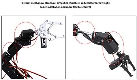
Image 3.3.1: Forearm mechanical structure, highlighting simplified design for easier installation and flexible control.
3.4. Attach the Gripper (Clamp Claw Manipulator)
- Assemble the clamp claw manipulator using its dedicated components and a servo motor for gripping action.
- Attach the assembled gripper to the end of the robotic arm structure.
3.5. Wiring and Connections
- Connect each servo motor to your control board (e.g., Arduino, not included) using the provided extension cords.
- Ensure all connections are secure and correctly oriented.
- Use the cable ties to manage and secure the wiring, preventing interference with moving parts.

Image 3.5.1: Fully assembled Qiilu 6DOF Robotic Arm Kit.
4. Operating Instructions
The Qiilu 6DOF Robotic Arm Kit requires an external control system (e.g., Arduino, Raspberry Pi) and programming to operate. This section provides general guidance.
4.1. Power Supply
- Connect a stable power supply with a voltage range of 4.8V-7.2V to your control board and subsequently to the servo motors.
- Ensure the power supply can provide sufficient current for all 6 servo motors under load.
4.2. Programming the Robotic Arm
- Develop or load appropriate code onto your control board to control each of the 6 servo motors.
- Each servo motor controls a specific joint, allowing for precise manipulation of the arm's position and the gripper's action.
- Refer to the documentation of your chosen control board and programming environment for specific coding instructions.
4.3. Initial Movement and Calibration
- Start with small, controlled movements for each joint to verify correct assembly and wiring.
- Calibrate the servo motors to ensure their full range of motion (180°) is utilized correctly and without mechanical strain.
- Avoid forcing the arm beyond its mechanical limits.

Image 4.3.1: Robotic arm in use, demonstrating assembly or testing.
5. Maintenance
Regular maintenance ensures the longevity and optimal performance of your robotic arm.
- Cleaning: Keep the robotic arm free from dust and debris. Use a soft, dry cloth for cleaning. Avoid using liquids directly on electronic components.
- Joint Inspection: Periodically check all joints and fasteners for looseness. Tighten any loose screws or nuts.
- Wiring Check: Inspect all wiring for fraying or damage. Replace any damaged wires immediately.
- Servo Performance: Monitor servo motor performance. If a servo becomes noisy or exhibits erratic movement, it may require replacement.
- Storage: When not in use, store the robotic arm in a clean, dry environment away from extreme temperatures and direct sunlight.
6. Troubleshooting
This section addresses common issues you might encounter.
| Problem | Possible Cause | Solution |
|---|---|---|
| Robotic arm does not move. | No power, incorrect wiring, faulty servo, programming error. | Check power supply (4.8V-7.2V), verify all wiring connections, test individual servos, review your control code. |
| Erratic or jerky movement. | Loose connections, insufficient power, mechanical obstruction, servo calibration issue. | Tighten all screws and nuts, ensure adequate power supply, check for obstructions, recalibrate servos. |
| Arm cannot lift objects. | Object too heavy, gripper not closing fully, servo torque insufficient. | Reduce object weight, check gripper servo operation and mechanical linkage, ensure servo is receiving full power. |
| Arm makes grinding noises. | Servo motor strain, mechanical interference, worn gears. | Reduce load, check for parts rubbing, inspect servo gears for damage and replace if necessary. |
7. Specifications

Image 7.1.1: Dimensional drawing of the robotic arm.
| Feature | Detail |
|---|---|
| Model Number | Qiilu6gud9eoafz |
| Color | Black |
| Material | Aluminium |
| Number of Degrees of Freedom (DOF) | 6 |
| Servo Motors | 6 x MG996 Analog Steering Gear |
| Working Voltage | 4.8V-7.2V |
| No-load Current | 100mA |
| Machine Torsion | 10kg.cm |
| Limit Angle | 180° |
| Gear Material | Metal gear |
| Dead Time | 5uS |
| Power Source | External Power Supply |
| Recommended Uses | Educational, Industrial, DIY Projects |
| Parcel Dimensions | 25.3 x 16.9 x 5.2 cm; 890 g |
8. Warranty and Support
For warranty information, please refer to the terms and conditions provided at the point of purchase or contact your retailer. For technical support, assembly assistance, or inquiries regarding your Qiilu 6DOF Robotic Arm Kit, please contact Qiilu customer service through the vendor's contact information provided with your purchase or via their official website.
Please have your model number (Qiilu6gud9eoafz) and purchase details ready when contacting support.