
1. Product Overview
The SEAFRONT ESP32 8-Channel Relay Module is a versatile development board designed for smart home control, IoT projects, and secondary ESP32 development. It integrates an ESP32-WROOM-32E module with 4MB Flash, providing WiFi and BLE connectivity. This board features 8 onboard 5V relays, programmable buttons, a reset button, and a programmable LED, making it suitable for controlling various loads with operating voltages between 250V AC and 30V DC.

Figure 1: Top-down view of the SEAFRONT ESP32 8-Channel Relay Module.
2. Package Contents
Upon opening the package, please verify that all the following components are included:
- 1 x SEAFRONT ESP32 8-Channel Relay Module
- 2 x 9-pin Dual Connectors
- 1 x 6-pin Single Connector
- 1 x Jumper Cap
3. Specifications
| Feature | Detail |
|---|---|
| Product Type | 8-Channel Relay Module |
| Material | PCB |
| Power Supply | DC 5-30V |
| Relay Type | 5V, 8-circuit onboard relays |
| Load Control Voltage | Up to 250V AC or 30V DC |
| Module | ESP32-WROOM-32E |
| Flash Memory | 4MB |
| Connectivity | WiFi, BLE |
| I/O Ports | All I/O ports exported for secondary development |
| Dimensions (L x W x H) | 19 x 12 x 2 cm |
| Weight | 134 grams |

Figure 2: Close-up view of the 8 relays and power input section.
4. Setup and Wiring
This section outlines the basic steps for connecting and powering your ESP32 Relay Module.
- Power Connection: Connect a DC 5-30V power supply to the designated power input terminals on the board. Ensure correct polarity.
- Load Connection: Connect your desired loads (e.g., lights, motors) to the relay terminals. Each relay provides normally open (NO) and common (COM) contacts. Refer to the silkscreen on the PCB for specific connections.
- Peripheral Connections: If using external sensors or other peripherals, connect them to the exposed I/O ports as required by your application.

Figure 3: The relay module integrated into a smart home concept. The board supports 4MB Flash capacity.
The module is designed for easy installation and use. All I/O ports and UART program download ports are exposed for convenient secondary development.
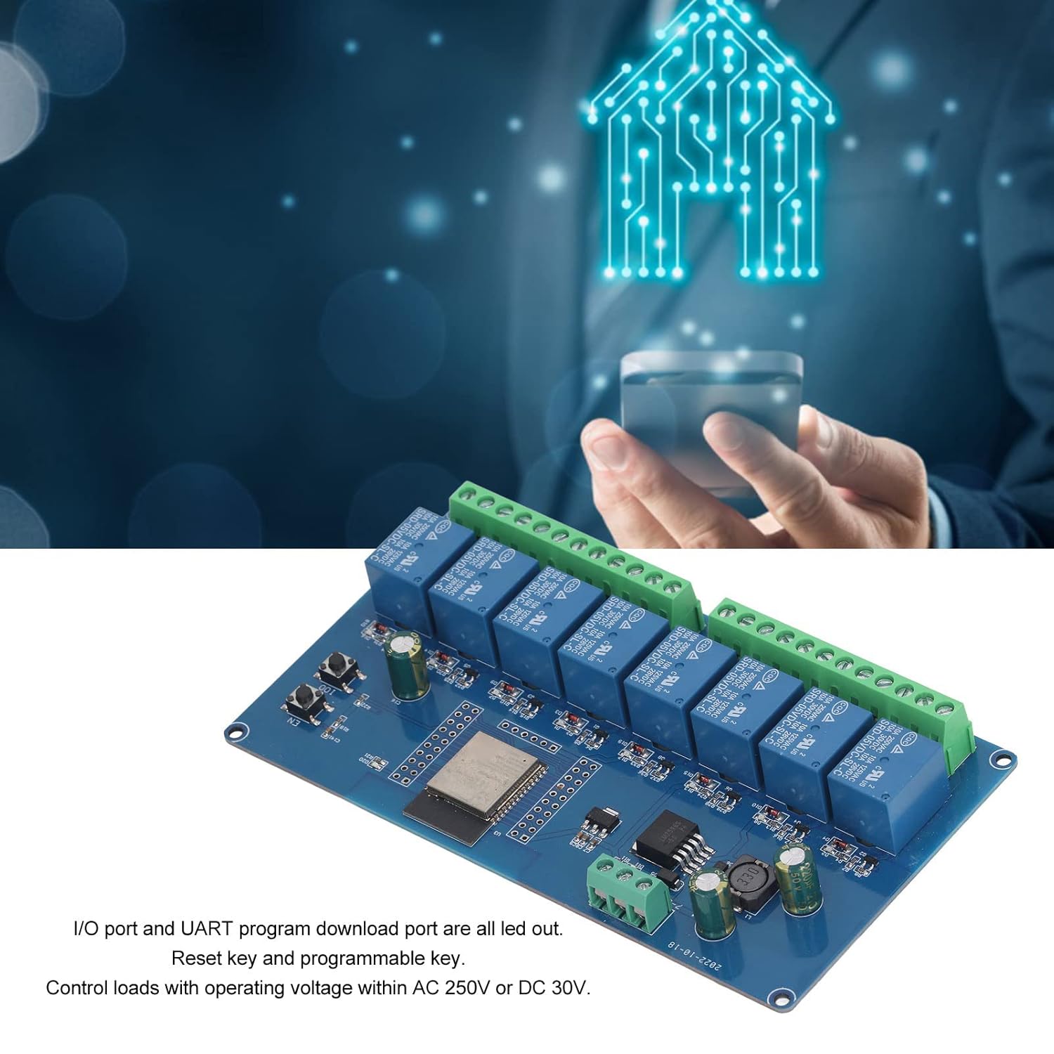
Figure 4: Overview of I/O ports, reset key, and programmable key on the module.
5. Operating Instructions and Programming
This module is primarily intended for programmable control. Basic operation involves uploading custom firmware to the ESP32 chip to control the relays via WiFi or BLE.
5.1. Relay Control
The 8 onboard relays are controlled by the ESP32 microcontroller. Each relay can be individually switched on or off through software commands. The relays are suitable for controlling loads with a working voltage up to 250V AC or 30V DC.
5.2. Programming the ESP32 Module
The ESP32-WROOM-32E module supports various development environments, including the Arduino IDE and ESP-IDF. To program the module, you will typically need a TTL USB serial converter.
- Connect the Serial Converter: Use a jumper cap to connect the 00 and GND pins on the ESP32 development board. Then, connect your TTL serial port module (e.g., FT232) to the computer's USB port. The connection between the serial port module and the ESP32 development board is as follows:
TTL Serial Port Module ESP32 Development Board GND GND TX RX RX TX 5V 5V - Select Board in IDE: In your development environment (e.g., Arduino IDE), select the board as "ESP32 Dev Module" under the Tools > Board menu.
- Open and Upload Program: Open your program code. In the Tools > Port menu, select the correct COM port number for your serial converter. Click "Upload" to compile and download the program to the ESP32 module.
- Disconnect and Reset: After successful upload, disconnect the connection between 00 and GND. Power cycle the development board or press the reset button to run your program.

Figure 5: Visual guide for programming the ESP32 module using a serial converter and Arduino IDE.
Relay Pin Assignments: Based on user feedback, the GPIO pins controlling the relays are typically: GPIO32, GPIO33, GPIO25, GPIO26, GPIO27, GPIO14, GPIO12, GPIO13. It is recommended to verify these assignments with your specific firmware or by testing.
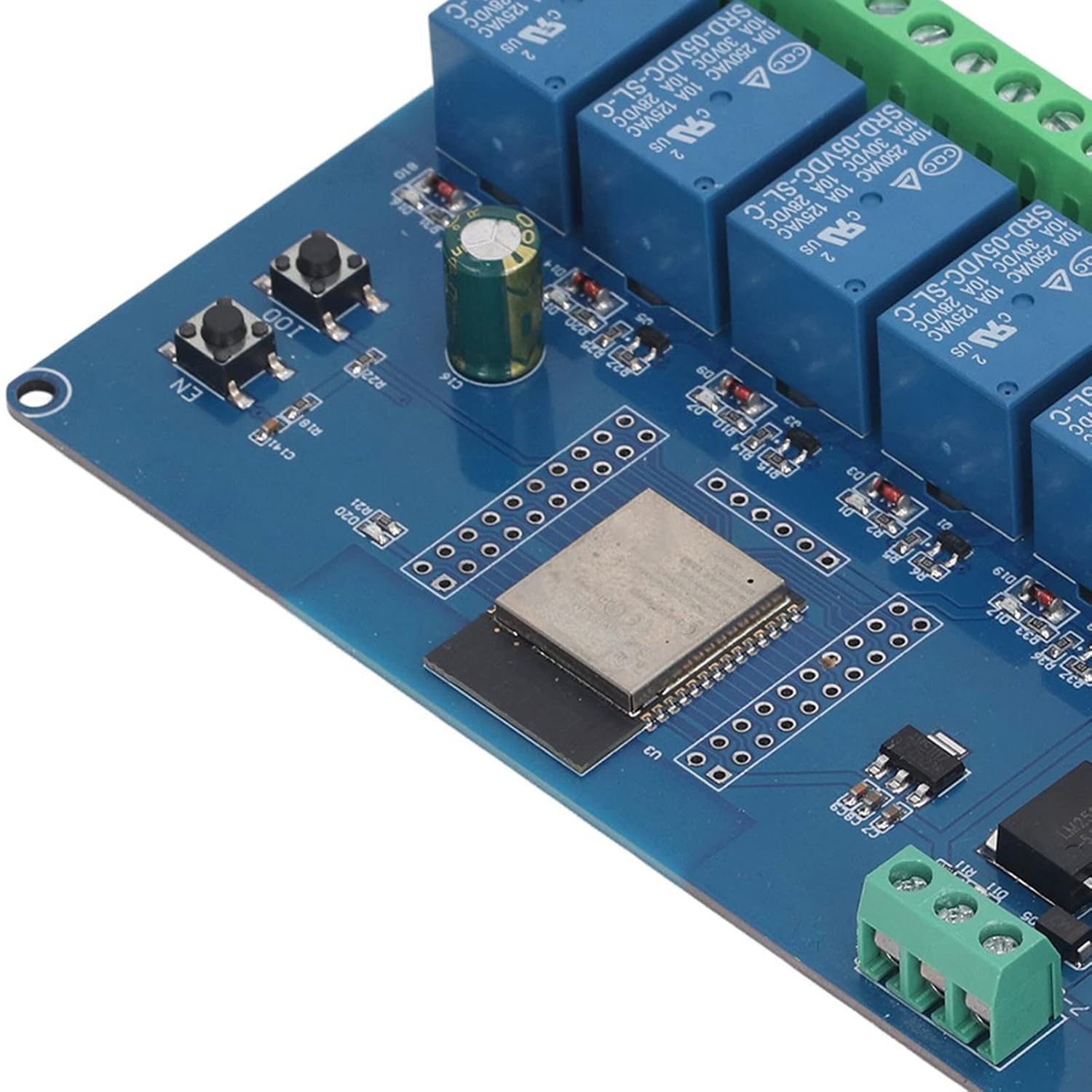
Figure 6: Close-up of the ESP32 module and onboard programmable buttons.
6. Troubleshooting
- Module Not Powering On:
- Ensure the DC power supply is within the 5-30V range and correctly connected to the power input terminals.
- Check for loose connections or damaged wires.
- Relays Not Actuating:
- Verify your program code is correctly uploaded and configured to control the specific relay GPIO pins.
- Ensure the load connected to the relay is within its voltage and current ratings.
- Check for proper wiring between the load and the relay terminals.
- Programming Issues:
- Confirm the TTL USB serial converter is correctly wired (TX to RX, RX to TX, GND to GND, 5V to 5V).
- Ensure the correct COM port is selected in your IDE.
- Verify that the 00 and GND pins are jumpered during programming and disconnected afterward.
- Check if the necessary ESP32 board definitions are installed in your IDE.
- WiFi/BLE Connectivity Problems:
- Ensure your firmware includes the necessary WiFi/BLE libraries and configuration.
- Check for strong signal strength in the operating environment.
- Verify network credentials if connecting to a WiFi network.
7. Maintenance
To ensure the longevity and reliable operation of your ESP32 Relay Module, follow these maintenance guidelines:
- Keep Clean: Regularly clean the board with a soft, dry brush to remove dust and debris. Avoid using liquids.
- Environmental Conditions: Operate the module within its specified temperature and humidity ranges. Avoid extreme conditions.
- Secure Connections: Periodically check all wiring connections to ensure they are secure and free from corrosion.
- Firmware Updates: Keep your ESP32 firmware updated to benefit from bug fixes and new features.
- Physical Protection: Consider housing the module in an enclosure to protect it from physical damage and environmental factors.

Figure 7: Close-up view of the terminal blocks for power and relay connections.
8. Warranty and Support
Specific warranty information for this product is not provided in the available documentation. For details regarding warranty coverage, returns, or technical support, please contact the seller or the manufacturer directly. Please refer to your purchase receipt or the seller's platform for contact information.