1. Introduction
The GATEXPERT IR13 Reflective Photoelectric Beam Sensor is designed to detect objects or obstructions within its sensing range. This sensor operates on a 12-24VDC power supply and features a relay contact output. Its IP54 waterproof rating makes it suitable for various indoor and outdoor applications, including compatibility with most gate and garage door openers. This manual provides essential information for the safe and effective installation, operation, and maintenance of your sensor.
2. Safety Information
- Power Supply: Ensure the power supply matches the sensor's requirements (12-24VDC ±10%). Incorrect voltage can damage the device.
- Wiring: All wiring should be performed by a qualified professional in accordance with local electrical codes. Disconnect power before performing any wiring or maintenance.
- Mounting: Securely mount the sensor and reflector to prevent accidental displacement, which could lead to false readings or damage.
- Environment: While the sensor is IP54 waterproof, avoid submerging it in water or exposing it to extreme temperatures beyond its operational limits.
- Intended Use: This sensor is intended for object detection and safety applications. Do not use it for life-critical systems without additional safety measures.
3. Package Contents
Verify that all components are present in the package:
- Reflective Photoelectric Beam Sensor unit with attached cable
- Reflector
- Mounting bracket
- Installation parts (screws, nuts)
- User manual
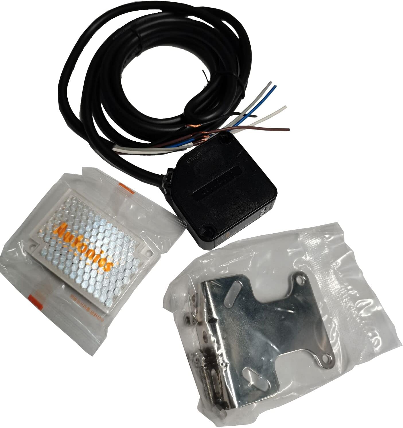
Image: Contents of the GATEXPERT IR13 sensor package, including the sensor, reflector, mounting bracket, and wiring.
4. Specifications
| Model Number | IR13 |
| Sensing Distance | 0.1 - 7 meters |
| Power Supply | 12-24VDC ±10% |
| Output Type | Relay Contact Output |
| Protection Rating | IP54 Waterproof |
| Dimensions | Approximately 3 x 3 x 1 inches (Sensor unit) |
| Weight | Approximately 8.4 ounces |
| Included Components | Reflective sensor, reflector, mounting parts, user manual |
5. Setup and Installation
5.1 Mounting the Sensor and Reflector
The sensor and reflector must be mounted opposite each other, ensuring a clear line of sight between them. The maximum sensing distance is 7 meters (approximately 23 feet).
- Choose Location: Select a stable, vibration-free surface for mounting both the sensor and the reflector. Ensure the path between them is free from permanent obstructions.
- Mount Sensor: Use the provided mounting bracket and screws to securely attach the sensor unit to your chosen surface.
- Mount Reflector: Mount the reflector directly opposite the sensor. The reflector should be at approximately the same height as the sensor.

Image: The metal mounting bracket included with the GATEXPERT IR13 sensor.

Image: The reflective panel (reflector) used with the GATEXPERT IR13 sensor.
5.2 Wiring Diagram
The GATEXPERT IR13 sensor uses a multi-wire cable for power and output. Refer to the following wiring guide:
- Brown Wire: Connect to +12-24VDC (Positive Power Supply)
- Blue Wire: Connect to 0VDC (Negative Power Supply / Ground)
- Black Wire: Common (COM) for Relay Output
- White Wire: Normally Open (NO) for Relay Output
- Gray Wire: Normally Closed (NC) for Relay Output
Connect the Brown and Blue wires to your 12-24VDC power source. The Black, White, and Gray wires are for the relay output, which can be connected to a gate opener, alarm system, or other control device. Consult your control device's manual for specific input requirements.

Image: Close-up of the GATEXPERT IR13 sensor showing the multi-colored wires for power and relay output.
5.3 Alignment
Proper alignment between the sensor and the reflector is crucial for reliable operation.
- Power On: Apply power to the sensor after completing the wiring.
- Initial Adjustment: Roughly aim the sensor towards the center of the reflector.
- Fine-tuning: Slowly adjust the angle of the sensor (and/or reflector) until the indicator light on the sensor (if present) illuminates steadily, or until your connected device indicates a clear beam.
- Test: Once aligned, pass an object through the beam path to confirm the sensor detects it and triggers the relay output as expected.
6. Operating Instructions
Once properly installed and aligned, the GATEXPERT IR13 sensor operates automatically:
- Beam Established: When there is a clear line of sight between the sensor and the reflector, the infrared beam is established. The relay output will be in its default state (e.g., NO contact open, NC contact closed).
- Object Detection: When an object breaks the infrared beam, the sensor detects the interruption.
- Relay Activation: Upon detection, the relay output changes state (e.g., NO contact closes, NC contact opens). This signal can be used to trigger a gate opener to stop, an alarm, or other safety functions.
- Beam Restored: Once the object moves out of the beam path, the sensor restores the beam, and the relay output returns to its default state.
7. Maintenance
Regular maintenance ensures optimal performance and longevity of your sensor:
- Cleaning: Periodically clean the sensor lens and the reflector surface with a soft, damp cloth. Dust, dirt, or debris can interfere with the infrared beam. Do not use abrasive cleaners.
- Alignment Check: Occasionally verify that the sensor and reflector remain properly aligned. Strong winds or physical impacts can shift their positions.
- Wiring Inspection: Check wiring connections for any signs of wear, corrosion, or loose connections. Ensure all connections are secure and protected from environmental elements.
- Environmental Factors: Clear any vegetation, spiderwebs, or other obstructions that may grow or accumulate in the beam path.
8. Troubleshooting
If the sensor is not functioning as expected, refer to the following troubleshooting guide:
| Problem | Possible Cause | Solution |
|---|---|---|
| Sensor not powering on (no indicator light) | No power supply; incorrect wiring; faulty power supply. | Check power connections (Brown to +VDC, Blue to 0VDC). Ensure power supply is active and within 12-24VDC range. Test power supply. |
| Sensor not detecting objects / False detections | Misalignment; dirty lens/reflector; obstruction in beam path; excessive sensing distance; strong sunlight interference. | Re-align sensor and reflector carefully. Clean sensor lens and reflector. Remove any obstructions. Ensure distance is within 0.1-7m. Consider shielding from direct sunlight if applicable. |
| Relay output not triggering | Incorrect wiring of relay contacts; faulty relay; issue with connected control device. | Verify Black, White, and Gray wire connections to your control device. Test the relay output with a multimeter if possible. Check the input requirements of your control device. |
| Intermittent operation | Loose connections; unstable power; partial obstruction; vibration. | Check all wiring connections for tightness. Ensure stable power supply. Clear beam path. Securely mount sensor and reflector to minimize vibration. |
9. Warranty and Support
GATEXPERT products are manufactured to high-quality standards. For specific warranty details, please refer to the warranty card included with your product or contact GATEXPERT customer support. If you encounter issues not covered in this manual, please reach out to GATEXPERT customer service for assistance.
Contact Information: Please refer to the GATEXPERT official website or product packaging for the most current customer support contact details.


