1. Introduction
This manual provides detailed instructions for the safe and effective use of your ANENG SZ301 Digital Multimeter. The SZ301 is a versatile, automatic range digital multimeter designed for measuring DC voltage, AC voltage, DC current, AC current, resistance, capacitance, diode, and continuity. It features a digital display with a maximum count of 2000, an automatic shutdown function, and a built-in NCV sensor for non-contact voltage detection. Please read this manual thoroughly before operation and retain it for future reference.
2. Safety Information
To ensure safe operation and service of the meter, follow these safety precautions:
- Always adhere to local and national safety codes.
- Do not use the meter if it appears damaged or if the insulation on the test leads is compromised.
- Never apply voltage or current that exceeds the specified maximum limits.
- Exercise extreme caution when working with voltages above 30V AC RMS, 42V peak, or 60V DC. These voltages pose a shock hazard.
- Always disconnect the test leads from the circuit before changing functions or ranges.
- Ensure the battery cover is securely closed before operating the meter.
- Replace batteries immediately when the low battery indicator appears to ensure accurate readings.
- The built-in NCV sensor detects AC voltage. An LED flash and buzzer sound indicate detection, helping prevent electric shock.
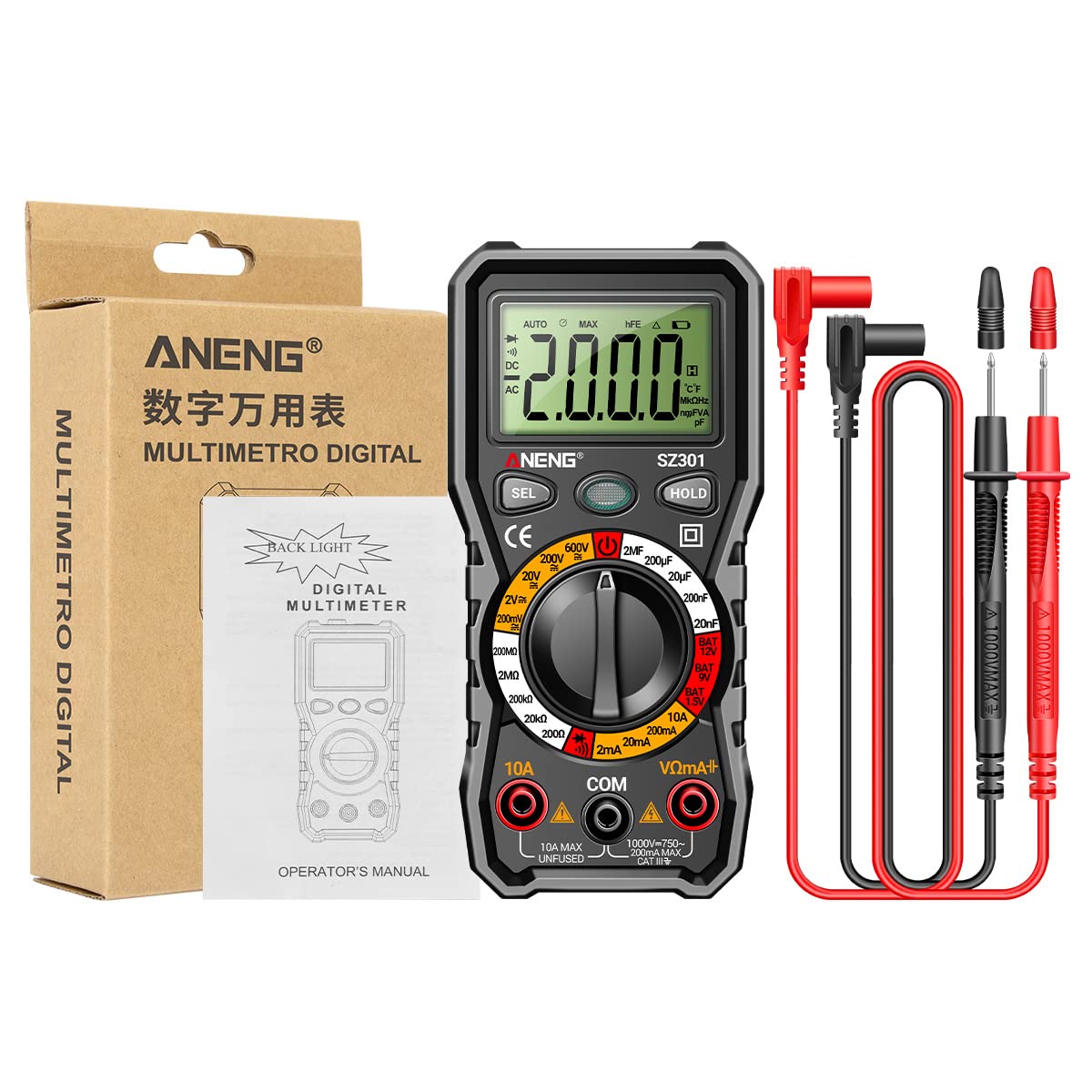
3. Product Overview
The ANENG SZ301 Digital Multimeter is designed for ease of use and durability. It features a robust silicone case for protection and a convenient pen holder/card slot.

Key Components:
- Digital Display: Shows measurement readings, units, and indicators.
- Function Switch Key (SEL): Used to select different measurement modes within a range (e.g., AC/DC voltage, Diode/Buzzer).
- Data Hold Key (HOLD): Freezes the current reading on the display. Long press for shutdown.
- Rotary Dial: Selects the primary measurement function (Voltage, Resistance, Capacitance, Current, Battery Test, Diode/Continuity).
- Input Jacks:
- COM Jack: Common (negative) input for all measurements.
- VΩmA+ Jack: Positive input for voltage, resistance, capacitance, diode, and small current measurements.
- 10A Jack: Positive input for high current (up to 10A) measurements.
- NCV Sensor: Non-Contact Voltage detection area.
- LED Light: For illuminating dark work areas.
- Low Battery Indicator: Icon on the display indicating low battery power.


4. Key Features
- Multifunctional: A fully functional multipurpose machine capable of measuring various electrical parameters.
- Built-in NCV Sensor: Non-Contact Voltage (NCV) measurement detects voltage in the air. An LED flashes and an alarm buzzer sounds when nearby AC voltage is detected, enhancing safety.
- Support Frame & Pen Holder: Features a built-in pen slot for easy carrying and an anti-drop, shock-proof storage slot. The 90-degree design of the rear bracket allows for convenient hands-free measurement.
- Automatic Shutdown: If the multimeter is not used within 15 minutes, it will automatically shut down to conserve battery power.
- LED Light & Backlight: Long press the appropriate button to turn on the LCD bright screen backlight, allowing clear visibility of values in dark environments. A flashlight function illuminates the front for night work assistance.

5. Setup
5.1 Battery Installation
- Ensure the multimeter is turned off and test leads are disconnected.
- Locate the battery compartment on the back of the device.
- Unscrew the battery compartment cover.
- Insert two (2) AA batteries, observing the correct polarity (+/-) as indicated inside the compartment.
- Replace the battery compartment cover and secure it with the screw.
5.2 Initial Power On
Turn the rotary dial from the 'OFF' position to any desired measurement function. The display will light up, indicating the meter is ready for use.
6. Operating Instructions
Before making any measurements, ensure the test leads are correctly inserted into the appropriate input jacks.
6.1 DC Voltage Measurement (V–)
- Turn the rotary dial to the 'V–' range (e.g., 200mV, 2V, 20V, 200V, 600V). The meter may automatically select the range.
- Insert the red test lead into the 'VΩmA+' jack and the black test lead into the 'COM' jack.
- Connect the test leads in parallel to the DC voltage source or component you wish to measure.
- Read the voltage value on the display.
6.2 AC Voltage Measurement (V∼)
- Turn the rotary dial to the 'V∼' range (e.g., 2V, 20V, 200V, 600V). The meter may automatically select the range.
- Insert the red test lead into the 'VΩmA+' jack and the black test lead into the 'COM' jack.
- Connect the test leads in parallel to the AC voltage source or component.
- Read the voltage value on the display.

6.3 Resistance Measurement (Ω)
- Turn the rotary dial to the 'Ω' range (e.g., 200Ω, 2kΩ, 20kΩ, 200kΩ, 2MΩ, 20MΩ).
- Insert the red test lead into the 'VΩmA+' jack and the black test lead into the 'COM' jack.
- Ensure the circuit or component is de-energized before measuring resistance.
- Connect the test leads across the component whose resistance you want to measure.
- Read the resistance value on the display.
6.4 Diode Test (→|)
- Turn the rotary dial to the 'Diode/Buzzer' position. Press the 'SEL' button if necessary to select Diode mode.
- Insert the red test lead into the 'VΩmA+' jack and the black test lead into the 'COM' jack.
- Connect the red test lead to the anode and the black test lead to the cathode of the diode.
- The display will show the forward voltage drop. Reverse the leads; the display should show 'OL' (Open Loop) for a good diode.

6.5 Capacitance Measurement (F)
- Turn the rotary dial to the 'F' (Capacitance) range (e.g., 2nF, 20nF, 200nF, 2µF, 20µF, 200µF).
- Insert the red test lead into the 'VΩmA+' jack and the black test lead into the 'COM' jack.
- Ensure the capacitor is fully discharged before measurement to prevent damage to the meter.
- Connect the test leads across the capacitor.
- Read the capacitance value on the display.
6.6 Current Measurement (A)
- For small currents (mA): Turn the rotary dial to the 'mA' range (e.g., 2mA, 20mA, 200mA). Insert the red test lead into the 'VΩmA+' jack and the black test lead into the 'COM' jack.
- For high currents (10A): Turn the rotary dial to the '10A' range. Insert the red test lead into the '10A' jack and the black test lead into the 'COM' jack.
- Ensure the circuit is de-energized. Open the circuit where you want to measure current.
- Connect the meter in series with the circuit. The current must flow through the meter.
- Re-energize the circuit and read the current value on the display.
6.7 Continuity Test (♫)
- Turn the rotary dial to the 'Diode/Buzzer' position. Press the 'SEL' button if necessary to select Continuity mode.
- Insert the red test lead into the 'VΩmA+' jack and the black test lead into the 'COM' jack.
- Ensure the circuit or component is de-energized.
- Connect the test leads across the component or wire.
- If continuity exists (resistance below a certain threshold), the buzzer will sound.
6.8 Battery Test (BAT)
- Turn the rotary dial to the 'BAT' position (1.5V, 9V, 12V).
- Insert the red test lead into the 'VΩmA+' jack and the black test lead into the 'COM' jack.
- Connect the red test lead to the positive terminal and the black test lead to the negative terminal of the battery.
- Read the battery voltage on the display.
6.9 NCV (Non-Contact Voltage) Detection
- Turn the rotary dial to the 'NCV' position.
- Move the top part of the multimeter (where the NCV sensor is located) close to the AC voltage source (e.g., an electrical outlet or live wire).
- If AC voltage is detected, the LED indicator will flash, and the buzzer will sound, with the frequency increasing as the meter gets closer to the voltage source.
7. Maintenance
7.1 Cleaning
Wipe the case with a damp cloth and mild detergent. Do not use abrasives or solvents. Ensure the meter is completely dry before use.
7.2 Battery Replacement
When the low battery indicator appears on the display, replace the batteries as described in the 'Battery Installation' section (5.1). Always use two new AA batteries.
7.3 Storage
If the meter is not to be used for an extended period, remove the batteries to prevent leakage and damage. Store the meter in a cool, dry place, away from direct sunlight and extreme temperatures.
8. Troubleshooting
- Meter does not power on: Check battery installation and ensure batteries are not depleted.
- No reading or 'OL' displayed: Ensure test leads are properly connected to the circuit and the correct function/range is selected. 'OL' often indicates an open circuit or a value exceeding the selected range.
- Inaccurate readings: Check battery level. Ensure test leads are making good contact. Verify the correct function and range are selected for the measurement.
- Automatic shutdown: This is a normal power-saving feature. Turn the rotary dial to 'OFF' and then back to the desired function to restart.
9. Specifications
| Parameter | Value |
|---|---|
| Display Type | Digital display |
| Model Number | SZ301 |
| DC Voltage Range | 200mV - 600V |
| AC Voltage Range | 0V - 600V |
| Max Count | 2000 |
| Power Source | 2 x AA battery (not included) |
| Shell Material | ABS |
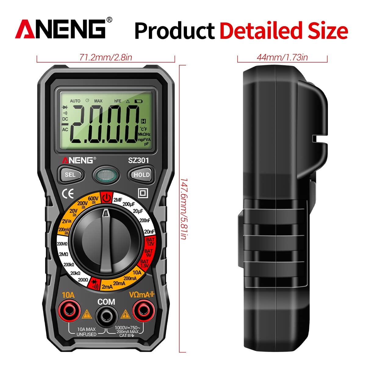
| Size | Approx. 147.7 x 70.3 x 42.5mm (5.81 x 2.77 x 1.67in) |
| Color | Black |
| Measurement Type | Ammeter, Multimeter |
| Manufacturer | GOLDEN BLUE |
| Date First Available | April 14, 2023 |
10. Warranty and Support
For warranty information or technical support, please refer to the documentation provided with your purchase or contact the retailer/manufacturer directly. Keep your proof of purchase for any warranty claims.


