
1. Introduction
This manual provides detailed instructions for the installation, operation, and maintenance of the Tycon Solar TP-SC24-30N-MPPT Solar Charge Controller. This device is designed to efficiently manage power flow from solar panels to batteries, ensuring optimal charging and protection for various battery types.
Key Features:
- 12/24V Autodetect 30A MPPT Smart Temp Compensated Solar Charge Controller with Status Display and Load Control.
- Automatic detection of 12V or 24V battery systems.
- Supports Wet, AGM, Gel, Lithium, and custom battery charging profiles.
- Integrated status display showing solar voltage, solar current, battery voltage, battery current, and load current.
- 30A solar input capacity and 20A negative ground load output.
- RS485 interface for remote monitoring and control.
2. Safety Information
Please read all instructions carefully before installation and operation. Failure to follow these instructions may result in damage to the unit, personal injury, or property damage.
- Ensure all wiring is correctly polarized and securely connected.
- Do not connect solar panels with an open-circuit voltage exceeding the controller's maximum input voltage.
- Always connect the battery first, then the solar panel, and finally the load. Disconnect in the reverse order.
- Install the controller in a well-ventilated area, away from flammable materials and direct sunlight.
- This device is not waterproof. Avoid exposure to moisture.
- Only qualified personnel should perform installation and maintenance.
3. Product Overview and Components
The TP-SC24-30N-MPPT controller features a compact design with an integrated LCD display for real-time system monitoring and robust terminals for secure connections.
Front Panel:

Figure 1: Front view of the TP-SC24-30N-MPPT controller. This image shows the main body of the solar charge controller, highlighting its integrated LCD screen which displays various system parameters, and the control buttons (PV, BAT, DC, S) used for navigation and settings adjustment.
The front panel includes the LCD display, which provides information on solar input, battery status, and load output. Control buttons allow for navigation through display screens and adjustment of settings.
Rear Panel and Terminals:
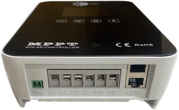
Figure 2: Rear view of the TP-SC24-30N-MPPT controller. This image displays the rear of the unit, clearly showing the various screw terminals for connecting the temperature sensor, solar panels (PV+ and PV-), battery (BAT+ and BAT-), DC load (LOAD+ and LOAD-), and the RS485 communication port.
The rear panel houses all necessary connection terminals:
- Temp: Temperature sensor input.
- PV+ / PV-: Solar panel input terminals.
- BAT+ / BAT-: Battery connection terminals.
- LOAD+ / LOAD-: DC load output terminals.
- RS485: Communication port for remote monitoring.
4. Setup and Installation
4.1 Mounting the Controller
The controller supports both DIN rail and wall mounting. Choose a location that is dry, well-ventilated, and protected from direct sunlight and moisture. Ensure adequate space around the controller for heat dissipation.
4.2 Wiring Connections
Follow the connection order precisely to avoid damage. Use appropriate wire gauges for your system's current requirements.

Figure 3: System wiring diagram. This diagram illustrates the typical connection setup for the solar charge controller, showing how the solar array, battery bank, and DC load are connected to the controller. It also indicates optional connections for a temperature sensor, WiFi module, and PC software via RS485.
- Connect the Battery: Connect the positive and negative terminals of the battery to the BAT+ and BAT- terminals on the controller. Ensure correct polarity. The controller will automatically detect 12V or 24V.
- Connect the Solar Panels: Connect the positive and negative leads from your solar array to the PV+ and PV- terminals. Ensure the solar panel's open-circuit voltage does not exceed the controller's maximum input voltage.
- Connect the DC Load (Optional): Connect your DC loads to the LOAD+ and LOAD- terminals. Ensure the total current draw does not exceed 20A.
- Connect Temperature Sensor (Optional): For accurate temperature compensation, connect the external temperature sensor to the 'Temp' terminal.
- Connect RS485 (Optional): For remote monitoring and control, connect an RS485 cable to the designated port.
4.3 Battery Type Selection
The controller supports various battery types. Refer to the controller's menu for selecting the appropriate battery type (Wet, AGM, Gel, Lithium, or Custom) to ensure correct charging parameters.
5. Operating Instructions
5.1 LCD Display Information
The LCD display provides real-time operational data. Use the control buttons (PV, BAT, DC, S) to cycle through different display screens:
- Solar Voltage (PV): Displays the current voltage from the solar panels.
- Solar Current (PV): Displays the current flowing from the solar panels.
- Battery Voltage (BAT): Displays the current battery voltage.
- Battery Current (BAT): Displays the current flowing into or out of the battery.
- Load Current (DC): Displays the current being drawn by the DC loads.
- System Status: Icons and indicators for charging status, battery level, and fault conditions.
5.2 Load Control
The controller features programmable load control. This allows you to set timers or voltage thresholds for turning the DC load output on or off, protecting the battery from over-discharge.
5.3 RS485 Communication
The RS485 interface enables connection to a computer or other monitoring devices for advanced system management, data logging, and remote control. Refer to the separate software manual for detailed instructions on using the RS485 interface.
6. Maintenance
Regular maintenance ensures optimal performance and longevity of your solar charge controller.
- Cleaning: Periodically clean the controller's exterior with a dry cloth. Ensure ventilation openings are free from dust and debris.
- Connection Checks: Annually inspect all wiring connections for tightness and corrosion. Loose connections can cause overheating and poor performance.
- Battery Inspection: Regularly check battery terminals for corrosion and ensure proper electrolyte levels for flooded batteries.
- System Monitoring: Monitor the display for any unusual readings or fault indicators.
7. Troubleshooting
This section addresses common issues you might encounter with the TP-SC24-30N-MPPT controller.
| Problem | Possible Cause | Solution |
|---|---|---|
| No display/No power | Battery not connected or low voltage; reversed polarity. | Check battery connections and voltage. Ensure correct polarity. |
| Battery not charging | Solar panels not connected; low solar input; faulty solar panel; incorrect battery type setting. | Verify solar panel connections. Check solar panel output. Confirm battery type setting. |
| Load not working | Load disconnected; overcurrent protection; battery low voltage disconnect. | Check load connections. Reduce load. Charge battery. |
| Inaccurate readings | Loose connections; faulty sensor. | Check all wiring connections. Inspect temperature sensor if applicable. |
8. Specifications
Technical specifications for the Tycon Solar TP-SC24-30N-MPPT Solar Charge Controller.
| Parameter | Value |
|---|---|
| Model | TP-SC24-30N-MPPT |
| System Voltage | 12V/24V Auto Detect |
| Max Solar Input Current | 30A |
| Max Load Output Current | 20A |
| Battery Types Supported | Wet, AGM, Gel, Lithium, Custom |
| Display Type | LCD |
| Communication Interface | RS485 |
| Mounting | DIN Rail / Wall Mount |
| Color | Black |
9. Contact and Support
For further assistance, technical support, or warranty inquiries, please contact Tycon Solar customer service or visit the official Tycon Solar website.
Website: www.tyconsystems.com


