
1. Introduction
Thank you for choosing the Greluma ZL591LUM Mini Infrared Motion Detector. This device is designed for indoor use to provide automatic lighting control and enhanced security. This manual provides essential information for safe installation, operation, and maintenance of your motion detector. Please read it thoroughly before installation and keep it for future reference.
2. Safety Information
WARNING: Electrical installation should only be performed by a qualified electrician. Incorrect installation can lead to electric shock, fire, or damage to the device.
- Always disconnect power at the main circuit breaker before installation or maintenance.
- Ensure the supply voltage matches the device's specifications (220-240V).
- Do not install in areas with high humidity or direct water exposure, as the device has an IP20 rating for indoor, dry environments only.
- Avoid installing near heat sources, air conditioning vents, or in direct sunlight, as this may affect sensor performance.
- Do not overload the sensor with connected lighting exceeding the specified maximum wattage.
3. Product Overview
The Greluma ZL591LUM is a compact infrared motion detector consisting of a control unit and a separate sensor head, designed for discreet ceiling installation. It detects movement within its 360° field of view and automatically switches connected lights on or off based on ambient light conditions and user-defined settings.

Figure 3.1: Complete Greluma ZL591LUM assembly showing the control unit, sensor head, and connecting wires.
3.1 Components
- Control Unit: Houses the electronic circuitry and DIP switches for setting adjustments. It has two mounting tabs for secure installation.
- Sensor Head: The infrared (PIR) detection component, designed for flush ceiling mounting.
- Connecting Cable: Links the sensor head to the control unit.
- Power and Load Wires: For connecting to the main power supply and the lighting fixture.
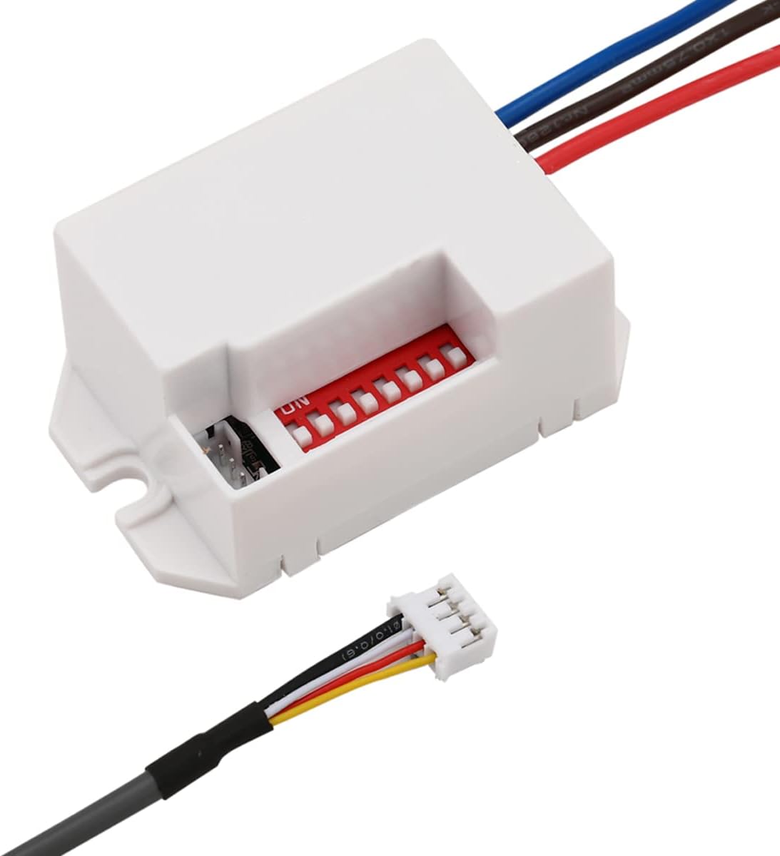
Figure 3.2: The control unit showing input/output wiring and the connector for the sensor head.
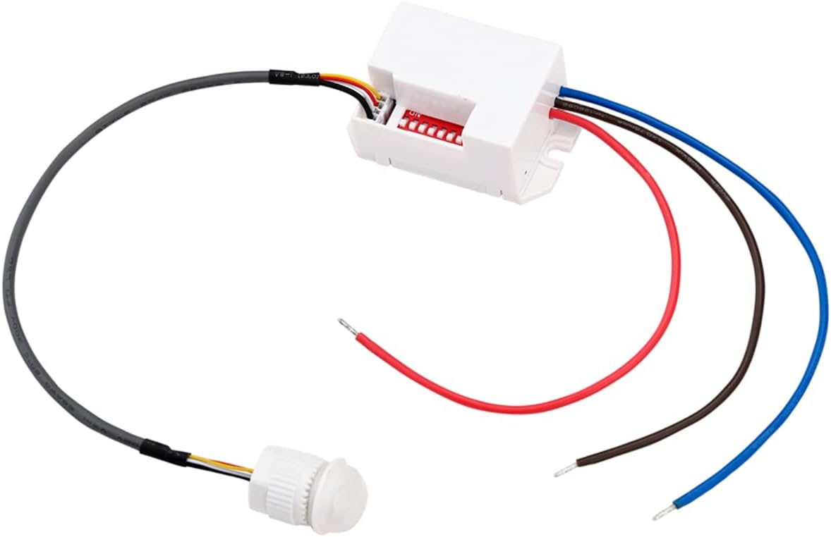
Figure 3.3: The compact sensor head with its integrated cable for connection to the control unit.
4. Specifications
| Feature | Specification |
|---|---|
| Model Number | ZL591LUM |
| Operating Voltage | 220-240V AC |
| Rated Load (Incandescent) | Max 800W |
| Rated Load (LED/Energy Saving) | Max 200W |
| Detection Angle | 360° |
| Detection Range | Up to 8 meters |
| Ambient Light Sensitivity (LUX) | Adjustable 10-2000 Lux |
| Time Delay | Adjustable (5s, 30s, 1min, 3min, 5min, 8min) |
| Installation Height | 2m to 4m |
| Protection Class | IP20 (Indoor use only) |
| Humidity | <93% RH (non-condensing) |
| Mounting Type | Ceiling Mount |

Figure 4.1: Dimensions of the sensor head and control unit (Unit: mm).
5. Setup and Installation
The Greluma ZL591LUM is designed for ceiling mounting. The control unit must be installed in a dry, protected area, such as above a false ceiling or within a junction box, due to its IP20 rating.
5.1 Installation Location
- Choose a central location on the ceiling for the sensor head to ensure optimal 360° detection.
- Ensure the installation height is between 2 meters and 4 meters for effective detection.
- Avoid placing the sensor near large metallic objects, glass, or moving air currents that could interfere with detection.
5.2 Wiring Diagram
Before wiring, ensure the power supply is OFF at the circuit breaker.
- Connect the Live (L) wire from the main power supply to the Live input terminal on the control unit (usually marked 'L' or red wire).
- Connect the Neutral (N) wire from the main power supply to the Neutral input terminal on the control unit (usually marked 'N' or blue wire).
- Connect the Live output wire from the control unit (usually marked 'L'' or brown wire) to the Live input of your lighting fixture.
- Connect the Neutral wire from your lighting fixture to the Neutral input terminal on the control unit (blue wire, shared with main neutral).
- Plug the sensor head's cable into the dedicated connector on the control unit.
Refer to the wiring diagram provided with the product for specific color codes if they differ from standard.
6. Operating Instructions
The Greluma ZL591LUM features adjustable settings via DIP switches located on the control unit. These settings allow you to customize the sensor's behavior to suit your specific needs.

Figure 6.1: Control unit with DIP switches for adjusting settings.
6.1 Adjusting Settings
Use a small tool (e.g., a pen tip) to adjust the DIP switches. Refer to the labels on the control unit for specific switch functions.
- Full-time/Night Work: This setting determines when the sensor is active. 'Full-time' means it will detect motion regardless of ambient light. 'Night work' means it will only activate when the ambient light falls below a certain threshold (adjustable LUX setting).
- Sensing Distance Adjustment: This allows you to fine-tune the detection range of the sensor, typically from a few meters up to 8 meters. Adjust according to the size of the room and desired coverage.
- Delay Time Switch (5s-8min): This sets how long the light remains on after the last detected motion. Available options usually include 5 seconds, 30 seconds, 1 minute, 3 minutes, 5 minutes, and 8 minutes.
6.2 Operation Logic
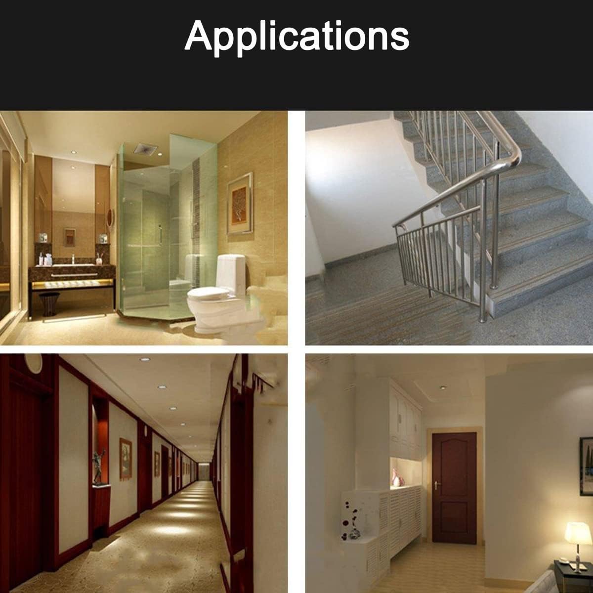
Figure 6.2: Work Diagram illustrating sensor behavior.
- Daytime/Bright Light: If the ambient light is sufficient (above the set LUX threshold), the lights will not turn on even if motion is detected.
- Nighttime/Low Light (No Motion): If the ambient light is low (below the set LUX threshold) and no motion is detected, the lights will remain off.
- Nighttime/Low Light (Motion Detected): If the ambient light is low and motion is detected, the lights will turn on automatically.
- Lights Off After Motion Ceases: After motion is no longer detected, the lights will remain on for the set delay time and then turn off automatically.
7. Maintenance
The Greluma ZL591LUM motion detector requires minimal maintenance.
- Cleaning: Periodically wipe the sensor lens with a soft, dry cloth to remove dust or debris that might obstruct detection. Do not use abrasive cleaners or solvents.
- No User-Serviceable Parts: Do not attempt to open or repair the control unit or sensor head. Doing so will void the warranty and may pose a safety risk.
8. Troubleshooting
If you experience issues with your motion detector, refer to the following common problems and solutions:
| Problem | Possible Cause | Solution |
|---|---|---|
| Lights do not turn on when motion is detected. |
|
|
| Lights stay on continuously. |
|
|
| Lights turn on without apparent motion (false triggers). |
|
|
| Detection range is too short or inconsistent. |
|
|
9. Applications
The Greluma ZL591LUM motion detector is suitable for a variety of indoor applications, enhancing convenience and energy efficiency:
- Hallways and Corridors: Automatically illuminate paths as people move through.
- Basements and Storage Rooms: Hands-free lighting when entering with items.
- Bathrooms and Toilets: Convenient lighting without needing to touch switches.
- Utility Rooms and Garages (Indoor): Provides light only when needed.
- Offices and Workspaces: Energy-saving lighting control.

Figure 9.1: Examples of typical indoor applications for the motion detector.
10. Warranty and Support
Greluma products are manufactured to high-quality standards. This product comes with a standard manufacturer's warranty against defects in materials and workmanship under normal use. Please retain your proof of purchase for warranty claims.
For technical support, troubleshooting assistance, or warranty inquiries, please contact your retailer or the Greluma customer service department through the contact information provided at the point of purchase.