
1. Introduction
This manual provides detailed instructions for the Shutao 2.8-inch TFT LCD Touch Screen Module, featuring the ILI9341 driver. This module is designed for embedded systems and DIY electronics projects, offering a 320x240 pixel resolution color display with touch functionality via a 4-wire SPI interface. It supports both 3.3V and 5V power supplies, making it versatile for various microcontrollers.
2. Features
- 2.8-inch color screen, supporting 65K color display for rich visuals.
- Utilizes a 4-wire SPI serial bus, requiring minimal I/O pins for display illumination.
- Integrated SD card slot for easy expansion and data storage.
- Includes touch screen function with a dedicated touch pen for interactive applications.
- 320x240 pixel resolution for clear image and text display.
3. Setup and Connections
Proper connection of the module to your microcontroller is crucial for correct operation. The module uses a 4-wire SPI interface for display control and additional pins for touch functionality and power.

Figure 3.1: Rear view of the 2.8-inch TFT LCD Touch Screen Module, showing the pinout connections and the integrated SD card slot. This view details the various pin connections for power, SPI communication, and touch functionality, along with the integrated SD card slot for expansion.
3.1 Pinout Description
| Pin Name | Description |
|---|---|
| VCC | Power supply input (3.3V to 5V) |
| GND | Ground |
| CS | LCD Chip Select (Active Low) |
| RESET | LCD Reset (Active Low) |
| DC | Data/Command Selection (High for Data, Low for Command) |
| MOSI | Master Out Slave In (SPI Data Input) |
| MISO | Master In Slave Out (SPI Data Output) |
| SCLK | SPI Clock |
| LED | Backlight Control (Connect to 3.3V for always on, or PWM for brightness control) |
| T_CS | Touch Screen Chip Select (Active Low) |
| T_CLK | Touch Screen SPI Clock |
| T_DIN | Touch Screen Data In |
| T_DO | Touch Screen Data Out |
| T_IRQ | Touch Screen Interrupt Request (Active Low) |
| SD_CS | SD Card Chip Select (Active Low) |
| SD_MOSI | SD Card SPI Data Input |
| SD_MISO | SD Card SPI Data Output |
| SD_SCK | SD Card SPI Clock |
3.2 Power Requirements
The module requires a VCC power supply between 3.3V and 5V. The logic IO port voltage for communication should be 3.3V (TTL). Ensure your microcontroller's logic levels are compatible or use level shifters if necessary to prevent damage.

Figure 3.2: The display module connected to a development board with multiple colored wires, illustrating a typical setup for integration into electronic projects. The screen is active, displaying an image.
4. Operating Instructions
4.1 Display Initialization and Control
The display is controlled via a 4-wire SPI interface. To operate the display, you will need to:
- Initialize the ILI9341 Driver: Send a sequence of commands to the ILI9341 driver IC to configure the display settings, such as resolution, orientation, and color mode. Refer to the ILI9341 datasheet for specific command sequences.
- Send Display Data: After initialization, pixel data can be sent via SPI. Set the DC pin high for data and low for commands. The MOSI pin carries the data, and SCLK provides the clock signal.
- Backlight Control: The LED pin controls the backlight. Connect it to 3.3V for continuous illumination or use a PWM signal from your microcontroller for adjustable brightness.

Figure 4.1: The 2.8-inch TFT LCD module in operation, displaying programming code. A hand is holding the provided touch pen, demonstrating the touch input capability of the screen.
4.2 Touch Screen Functionality
The module includes a resistive touch screen. The touch functionality is also controlled via SPI, using the T_CS, T_CLK, T_DIN, T_DO, and T_IRQ pins. The provided touch pen can be used for precise input.
- Touch Controller: The touch screen typically uses a separate controller IC (e.g., XPT2046, though not explicitly stated for this module, it's common for ILI9341 displays). You will need to initialize this controller and read touch coordinates.
- Reading Touch Input: When a touch is detected, the T_IRQ pin will go low. Your microcontroller can then read the X and Y coordinates by communicating with the touch controller via its dedicated SPI pins.
- Calibration: Resistive touch screens often require calibration to accurately map raw touch coordinates to display pixels.
4.3 SD Card Usage
The integrated SD card slot allows for storing images, fonts, or other data that can be displayed on the screen. The SD card communicates via its own SPI interface, using the SD_CS, SD_MOSI, SD_MISO, and SD_SCK pins. Standard SD card libraries can be used with your microcontroller to read and write data.
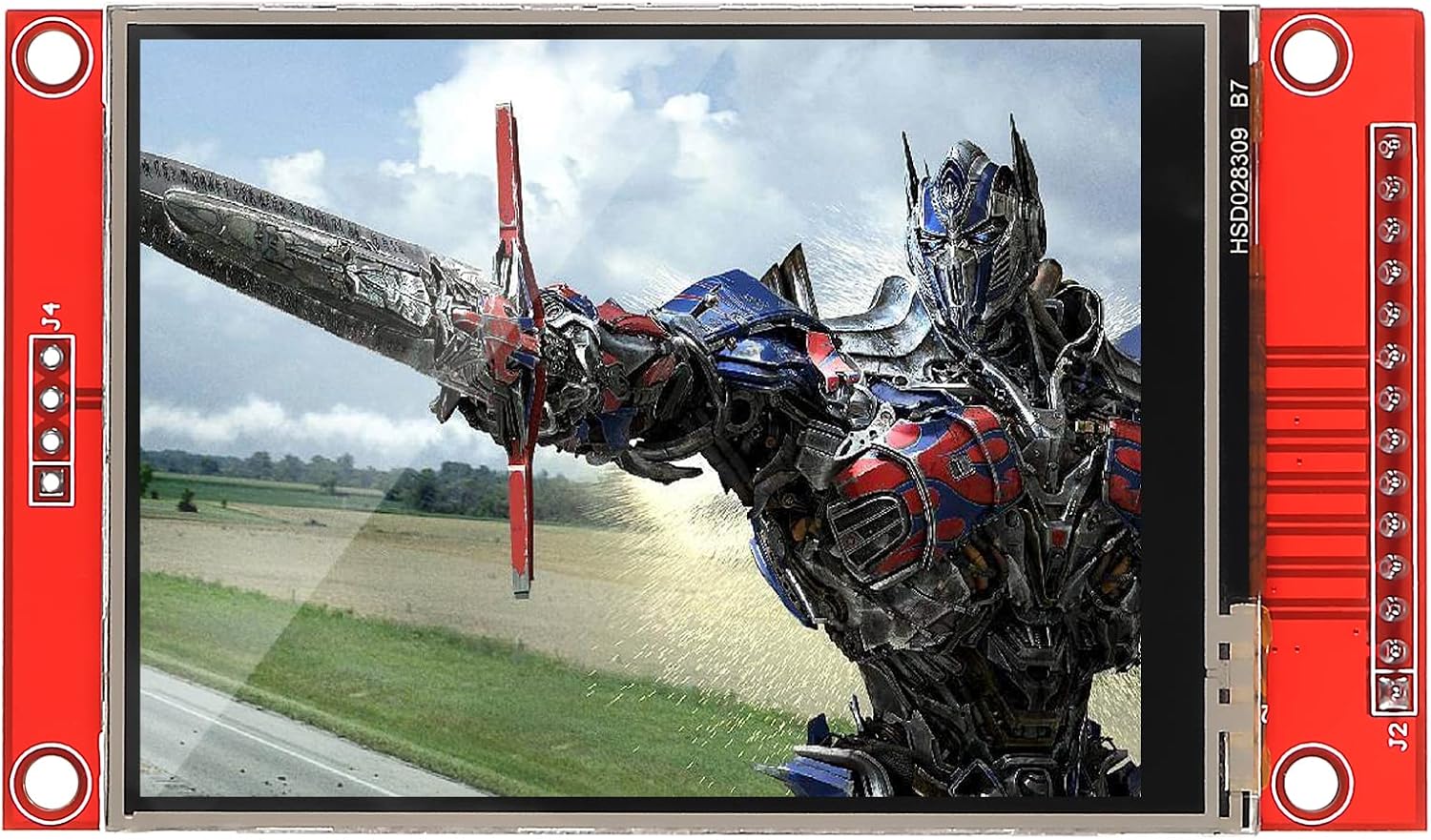
Figure 4.2: The module is shown displaying a vibrant image of a robot, highlighting its color display capabilities and 320x240 resolution.
5. Maintenance
To ensure the longevity and optimal performance of your TFT LCD module, follow these maintenance guidelines:
- Cleaning: Use a soft, lint-free cloth slightly dampened with water or a mild screen cleaner to gently wipe the display surface. Avoid abrasive materials or harsh chemicals.
- Handling: Always handle the module by its edges. Avoid applying pressure directly to the screen or the PCB components.
- Storage: Store the module in a dry, dust-free environment, away from direct sunlight and extreme temperatures.
- Static Electricity: Take precautions against electrostatic discharge (ESD) when handling the module, as electronic components are sensitive to static.
6. Troubleshooting
If you encounter issues with your 2.8-inch TFT LCD Touch Screen Module, consider the following troubleshooting steps:
- No Display/Blank Screen:
- Verify power connections (VCC and GND) are correct and stable.
- Check all SPI connections (CS, RESET, DC, MOSI, SCLK) for continuity and correct wiring.
- Ensure the backlight (LED pin) is properly powered.
- Confirm that the display initialization code is running correctly and without errors.
- Incorrect Colors/Garbled Display:
- Double-check the display initialization commands against the ILI9341 datasheet.
- Ensure the correct color mode (e.g., RGB565) is selected in your code.
- Verify SPI data transmission integrity.
- Touch Screen Not Responding:
- Check the touch screen SPI connections (T_CS, T_CLK, T_DIN, T_DO, T_IRQ).
- Ensure the touch controller is correctly initialized in your software.
- Verify that the T_IRQ pin is being monitored by your microcontroller.
- Perform touch screen calibration if necessary.
- SD Card Not Detected/Reading Errors:
- Ensure the SD card is properly inserted into the slot.
- Check the SD card SPI connections (SD_CS, SD_MOSI, SD_MISO, SD_SCK).
- Verify that your SD card is formatted correctly (e.g., FAT32).
- Test with a different SD card to rule out card issues.
7. Specifications

Figure 7.1: The display module presented alongside a table summarizing its technical specifications.
| Specification | Value |
|---|---|
| Screen Size | 2.8 inch |
| Display Type | TFT |
| Driver IC | ILI9341 |
| Resolution | 320x240 pixels |
| Module Interface | 4-wire SPI interface |
| VCC Power Voltage | 3.3V ~ 5V |
| Logic IO Port Voltage | 3.3V (TTL) |
| Touch Function | Yes |
| SD Card Slot | Yes |
| Item Weight | 1.44 ounces (approx. 40.8g) |
| Package Dimensions | 5.28 x 3.62 x 0.87 inches |
8. Package Contents
The package for the Shutao 2.8-inch TFT LCD Touch Screen Module typically includes:
- 1 x 2.8" SPI TFT LCD Display Module
- 1 x Touch Pen
9. Warranty and Support
For warranty information, technical support, or any inquiries regarding the Shutao 2.8-inch TFT LCD Touch Screen Module, please refer to the seller's return policy or contact the seller directly through the platform where the product was purchased. Keep your purchase receipt or order number handy for faster assistance.