Introduction
The BN-LINK Outdoor Digital Timer Box (Model CP-U49B) is a heavy-duty, 7-day programmable timer designed for various outdoor applications such as pool pumps, water heaters, fans, and SPA systems. This ETL Listed device provides reliable and efficient control over your electrical appliances.

Image: The BN-LINK Pool Pump Timer with its cover open, revealing the digital display, control buttons, and internal wiring terminals. Wiring diagrams and technical information are printed on the inside of the cover.
Product Features
- 40A Max Capacity: Capable of handling high electrical loads, including 2HP at 208-240VAC, 1HP at 120VAC, and 1HP at 277VAC.
- 7-Day Programmable: Offers flexible scheduling with up to 8 ON/OFF settings per day.
- Heavy Duty & Weatherproof: Constructed with a durable PC/ABS plastic shell, providing anti-oxidation and waterproof protection for outdoor use.
- ETL Listed: Conforms to UL 60730-1 and certified to CSA E60730-1 standards for safety and quality.
- Mounting & Padlock Holes: Designed for secure installation with integrated mounting and padlock features.

Image: Visual representation of the timer's key features, including its 40A maximum capacity, 7-day programmability, heavy-duty weatherproof design, and ETL certification.
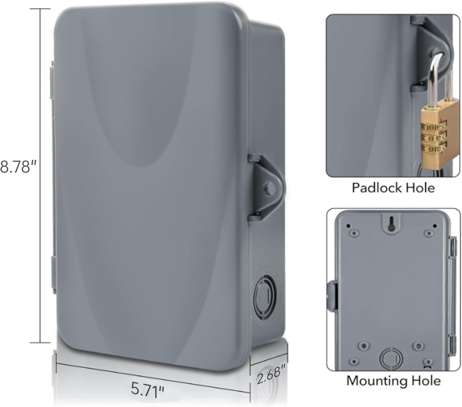
Image: Detailed view of the timer's dimensions (8.78" H x 5.71" W x 2.68" D) and close-ups of the padlock hole and mounting hole for secure installation.
Important Safety Warnings
Always have a qualified electrician install this product to avoid electric shock and ensure proper operation.
- Do not apply power to the timer until the DIP switch is set correctly for the input voltage.
- Ensure all power to the equipment being controlled is turned off at the circuit breaker before beginning installation or servicing.
- This unit is intended for the control of lighting, heating, air conditioning, pumps, motors, or general electrical circuits in residential, commercial, industrial, and agricultural facilities.
Setup and Installation
1. Setting the DIP Switch
Before applying power, set the DIP switch to match your input voltage. The DIP switch is located inside the timer box, under the protective cover.
- 120V: All four switches (1, 2, 3, 4) should be in the ON (up) position.
- 208/240V: Switch 1 ON, Switch 2 OFF, Switch 3 OFF, Switch 4 ON.
- 277V: All four switches (1, 2, 3, 4) should be in the OFF (down) position.

Image: Detailed view of the red DIP switch with four individual switches, indicating the correct ON/OFF positions for 120V, 208/240V, and 277V input voltages.
2. Wiring Instructions
Refer to the wiring diagrams provided on the inner panel of the timer and below. Always ensure power is OFF before wiring.

Image: Comprehensive wiring diagrams illustrating both SPDT (Single Pole Double Throw) and DPDT (Double Pole Double Throw) configurations for various voltage and load types.
120V Wiring (SPDT)
- Install a jumper wire from the left TIMER port to the COM1 port.
- Connect the Power Live Wire to the COM1 port.
- Connect the Power Neutral Wire and Load Neutral Wire to the right TIMER port.
- Connect the Load Live Wire to the NO1 port.
- Connect the Power Ground Wire and Load Ground Wire to the Ground Screw.
208/240V Wiring (DPDT)
- Install a jumper wire from the left TIMER port to the COM1 port.
- Install a second jumper wire from the right TIMER port to the COM2 port.
- Connect Power Live Wire 1 to the COM1 port.
- Connect Power Live Wire 2 to the COM2 port.
- Connect Load Neutral Wire 1 to the NO1 port.
- Connect Load Neutral Wire 2 to the NO2 port.
- Connect the Power Ground Wire and Load Ground Wire to the Ground Screw.
3. Mounting
External mounting tabs are provided for secure wall installation. Ensure the mounting surface is stable and appropriate for the timer's weight and outdoor environment.

Image: Close-up of the external mounting tabs, which can be used to securely attach the timer to a wall or other suitable surface.
Operation
1. Switch Operation
- ON Position (Switch Flipped Down): The unit will be continuously ON, regardless of programmed settings.
- OFF Position (Switch Flipped to Middle): The unit will be continuously OFF, regardless of programmed settings.
- AUTO Position (Switch Flipped Up): The unit will follow the programmed ON/OFF settings.
2. Power/Status Lights
- Red Power Indicator: Illuminates when power is applied to the timer.
- Green Status Indicator: Illuminates when power is applied to the connected loads.
3. Setting Current Time
- Press the RESET button with a small, non-metallic, insulated tool (e.g., pencil tip) to clear previous settings.
- Hold the CLOCK button and tap the WEEK button until the current day is displayed.
- Hold the CLOCK button and tap the HOUR button until the current hour is displayed.
- Hold the CLOCK button and tap the MIN button until the current minute is displayed.

Image: The timer's digital display and control buttons (WEEK, HOUR, MIN, MANUAL, PROG, CLOCK), highlighting the process of setting the current time.
4. Setting Programs (ON/OFF Schedules)
The timer must be displaying "AUTO" for programs to work. If not, hold down the MANUAL button until "AUTO" appears.
- Press the PROG button to enter program settings. You will see "1 ON" (setting the ON time for the first program).
- Press the WEEK button repeatedly to select the desired day combination for the program.
- Use the HOUR and MIN buttons to set the desired ON time.
- Press the PROG button again to set "1 OFF" (setting the OFF time for the first program).
- Repeat steps 2 and 3 to set the desired OFF time.
- Continue pressing PROG to set up to 8 ON/OFF schedules.
- To remove a program, press the R button while on that program. Press R again to restore it.
- Press the CLOCK button when finished to save programs and return to current time display.
5. Auto & Manual Override
- Auto Mode: The timer follows programmed schedules.
- Manual Override: Press the MANUAL button to temporarily toggle the output ON or OFF.
- "AUTO ON" means the device will stay ON until the next scheduled OFF time.
- "AUTO OFF" means the device will stay OFF until the next scheduled ON time.
- To disable all set schedules, hold down the MANUAL button until "MAN" (Manual) appears. In this mode, no schedules will run, and the power will stay ON or OFF as manually set.
6. Random Mode
To activate Random Mode, press the WEEK and HOUR buttons simultaneously. "RND" will appear on the display.
- When in Auto Mode with Random function ON, programmed ON/OFF times will be randomly postponed by 2 to 32 minutes.
- At least one ON/OFF program must be scheduled for Random Mode to function.
- All ON/OFF programs should have at least 33 minutes between the ON and OFF schedule for optimal random operation.
7. Daylight Saving Mode
To activate or deactivate Daylight Saving Time mode, press the HOUR and MIN buttons simultaneously. A "+1h" indicator will appear or disappear.
Note: This feature does not automatically adjust for yearly changes. You will need to manually toggle it ON or OFF as needed for daylight saving time.
Video: Official BN-LINK instructional video demonstrating the setup, wiring, and programming of the Outdoor Digital Pool Pump Timer Box. This video covers DIP switch settings, wiring for different voltages, setting current time, programming ON/OFF schedules, and using manual, random, and daylight saving modes.
Specifications
| Attribute | Value |
|---|---|
| Product Dimensions | 2.4 x 3.14 x 2.44 inches |
| Item Weight | 1.68 pounds |
| Item Model Number | CP-U49B |
| Brand | BN-LINK |
| Material | Plastic, Acrylonitrile Butadiene Styrene (PC/ABS) |
| Number of Settings | 8 (ON/OFF programs) |
| UPC | 810079581580 |
| Max Load | 40A, 2HP (120/240VAC), 1HP (277VAC) |
Troubleshooting
- Timer not turning ON/OFF as programmed:
- Ensure the switch is in the "AUTO" position.
- Verify that the current time and programmed schedules are set correctly.
- Check if Random Mode is active and affecting the schedule.
- No power to the unit:
- Confirm the circuit breaker supplying power to the timer is ON.
- Check all wiring connections for tightness and proper installation.
- Ensure the DIP switch is correctly set for the input voltage.
- Display is blank or erratic:
- Press the RESET button with a non-metallic tool.
- Verify stable power supply to the unit.
For more detailed troubleshooting steps or complex issues, please refer to the comprehensive user manual PDF or contact BN-LINK customer support.
Warranty and Support
For complete warranty information and customer support, please refer to the official user manual provided with your product. You can also download the PDF version of the user manual from the following link:
For further assistance, please visit the BN-LINK Store on Amazon or contact their customer service directly.
Ideal Applications
The BN-LINK Pool Pump Timer is versatile and suitable for controlling a variety of outdoor and heavy-duty electrical devices, including:
- Pool Pumps
- Fans
- Water Heaters
- Air Conditioning Blowers
- Outdoor Lighting
- SPA Systems

Image: A collage demonstrating various applications for the timer, including controlling a pool pump, industrial fans, outdoor lighting, and large air conditioning units.


