
Introduction
This instruction manual provides detailed guidance for the installation and use of the Reswish 50W 6ohm LED Load Resistor Conversion Kit. This product is designed to resolve common issues encountered when upgrading vehicle incandescent turn signal bulbs to LED, specifically hyper flash (rapid blinking) and bulb-out warning messages.
Safety Information
- Heat Generation: Load resistors generate significant heat during operation. It is crucial to mount them to a metal surface, such as the vehicle's chassis, and away from any plastic components, wiring, or other heat-sensitive materials to prevent damage or fire hazards.
- Electrical Safety: Always disconnect the vehicle's battery before performing any electrical work to prevent short circuits or electrical shock.
- Professional Installation: If you are not comfortable working with vehicle electrical systems, seek professional assistance for installation.
Package Contents
Verify that all components are present in your kit:
- Reswish 50W 6ohm Load Resistors (Quantity as per purchase)
- Quick Splice Wire Connectors (Matching quantity for resistors)

Image: Overview of the Reswish 50W 6ohm LED Load Resistor kit, showing two green resistors with attached red wires and four red quick splice connectors.
Installation Guide (Setup)
Follow these steps to properly install the load resistors:
- Prepare for Installation: Ensure the vehicle's ignition is off and the battery is disconnected. Access the wiring for the LED turn signal bulb you intend to correct.
- Identify Wires: Locate the positive (+) and negative (-) wires for the turn signal circuit. Typically, the positive wire carries the signal, and the negative wire is the ground. Refer to your vehicle's wiring diagram if unsure.
- Connect Resistor: The load resistor must be wired in parallel with the LED turn signal bulb. This means one wire from the resistor connects to the positive (+) wire of the turn signal circuit, and the other resistor wire connects to the negative (-) or ground wire of the turn signal circuit.

Image: A visual guide demonstrating how to connect the load resistor using quick splice connectors to the vehicle's turn signal wiring. The resistor connects across the 'Brake/Turn Signals +' wire and the 'Ground--' wire.
- Use Quick Splice Connectors: Insert the vehicle's turn signal wire (positive or negative) into one channel of a quick splice connector. Insert one of the resistor's red wires into the other channel. Close the connector firmly with pliers until it clicks, ensuring a secure connection. Repeat for the other resistor wire and the remaining turn signal wire.
- Secure Connections: Ensure all connections are tight and properly insulated.
- Mount the Resistor: Due to heat generation, mount the resistor securely to a clean, bare metal surface of the vehicle chassis using screws or high-temperature adhesive. Ensure it is away from any plastic, rubber, or other heat-sensitive materials.

Image: This diagram shows a 'correct' connection where the wire is fully inserted and crimped, and an 'incorrect' connection where the wire is loose or partially inserted, highlighting the importance of secure wiring.
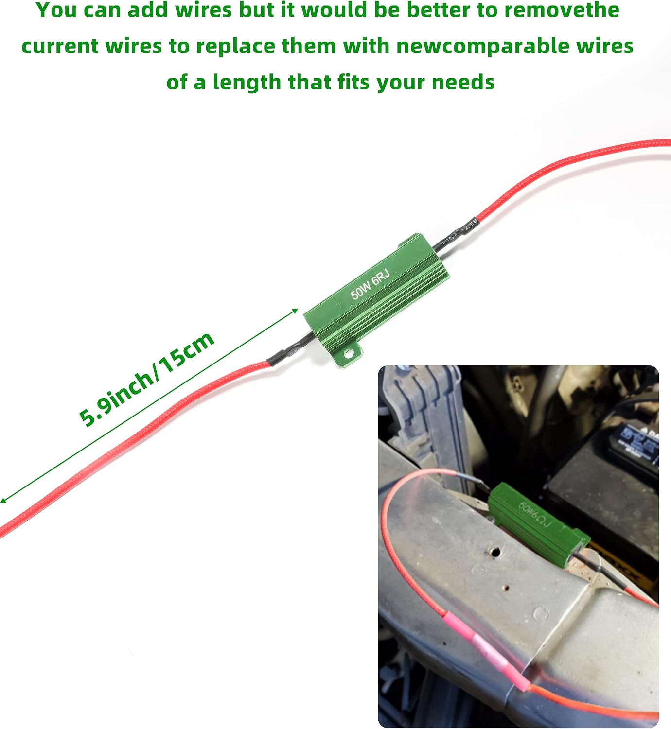
Image: A load resistor with a 5.9-inch (15cm) wire length indicated. The image suggests that while wires can be added, it is preferable to replace the current wires with new, comparable wires of a suitable length for your specific installation needs.
- Test Functionality: Reconnect the vehicle's battery. Test the turn signals to ensure they flash at the normal rate and that no error messages appear on the dashboard.
Operation
Once correctly installed, the Reswish 50W 6ohm LED Load Resistor operates automatically. It simulates the electrical load of a traditional incandescent bulb, tricking the vehicle's flasher relay or computer system into recognizing the LED bulb as a standard bulb. This prevents hyper flash and eliminates bulb-out warnings.
- Normal Flash Rate: Your LED turn signals should now flash at the standard, intended rate.
- Heat: It is normal for the resistor to become warm or hot during extended use of the turn signals. This is part of its normal operation as it dissipates excess electrical energy as heat. Ensure proper mounting as described in the Safety Information.
Maintenance
The Reswish load resistors are designed for durability and generally require minimal maintenance. However, periodic checks can ensure continued optimal performance:
- Connection Inspection: Periodically check the wire connections to ensure they remain secure and free from corrosion.
- Mounting Security: Verify that the resistor remains firmly mounted to its metal surface and has not come loose.
- Environmental Protection: Keep the resistors free from excessive moisture, dirt, and debris.
Troubleshooting
If you encounter issues after installation, consider the following:
- Hyper Flash Persists:
- Check Wiring: Ensure the resistor is wired correctly in parallel with the turn signal bulb (one wire to positive, one to ground). Incorrect wiring (e.g., in series) will prevent it from functioning.
- Verify Connections: Ensure all quick splice connectors are fully closed and making good contact with both the vehicle's wires and the resistor's wires. Loose connections are a common cause of failure.
- Resistor Functionality: If you have multiple resistors, try swapping them to see if one is faulty.
- No Turn Signal Function:
- Check for Short Circuits: Inspect all wiring for any exposed wires that might be touching metal or other wires, causing a short.
- Fuse Check: A short circuit could blow a fuse. Check your vehicle's fuse box for any blown fuses related to the turn signal circuit.
- Wire Breakage:
- Gentle Handling: Wires can be delicate. Ensure careful handling during installation to prevent breakage, especially at the resistor connection points.
Specifications
| Feature | Specification |
|---|---|
| Power Rating | 50 Watts |
| Resistance | 6 Ohms |
| Compatibility | 12V DC Vehicle Systems |
| Resistor Body Dimensions | Approximately 2 inches (5 cm) length, 3 cm width |
| Wire Length (each side) | Approximately 5.9 inches (15 cm) |
| Model Number | DZ001 |

Image: The load resistor body measures approximately 2 inches (5 cm) in length and 3 cm in width.
Warranty Information
Reswish products are typically covered by a limited manufacturer's warranty against defects in materials and workmanship. For specific warranty terms, duration, and claim procedures, please refer to the product packaging or contact the seller directly. Keep your proof of purchase for warranty claims.
Customer Support
If you have any questions, require technical assistance, or encounter issues not covered in this manual, please contact the seller or manufacturer through the platform where the product was purchased. Provide your order details and a clear description of the issue for prompt support.