
1. Introduction and Overview
The CEM DT-3398B Series Professional True RMS Clamp Meter is designed to provide accurate AC and AC/DC current and voltage readings, irrespective of waveform distortions. This instrument is suitable for a wide range of industrial and commercial applications, particularly where non-linear loads may affect current or voltage waveforms.
Key features include:
- AC/DC 2000A Current measurement with a 2-inch (52mm) jaw opening.
- 6000 counts LCD display for clear readings.
- True RMS measurements for accurate readings on non-sinusoidal waveforms.
- Measuring Voltage Range: 1000V AC/DC.
- Measuring Resistance Range: 60MΩ.
- Measuring Capacitance Range: 10mF.
- NVC (Non-Contact Voltage) Detection.
- Built-in Flashlight for illuminated work areas.
- Bluetooth connectivity for data transmission.
- Electronic overload protection: CAT IV 1000V.
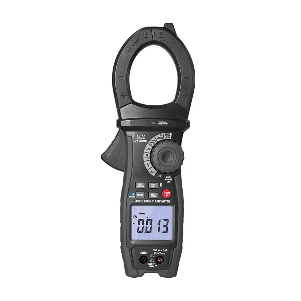
Figure 1: Front view of the CEM DT-3398B Clamp Meter, showing the display, rotary dial, and function buttons.
2. Safety Information
Read and understand all safety information before operating this meter. Failure to follow these instructions may result in electric shock, fire, or serious injury.
- CAT IV 1000V Rating: This meter is rated for CAT IV 1000V, indicating its suitability for measurements at the source of the low-voltage installation, such as electricity meters and primary overcurrent protection devices.
- Electrical Shock Hazard: Always assume that any circuit is live until proven otherwise. Do not touch exposed conductors or circuit components.
- Proper Use: Use the meter only as specified in this manual. Do not exceed the maximum input limits for any function.
- Inspection: Before each use, inspect the meter, test leads, and accessories for any damage. Do not use if damaged.
- Battery Replacement: Ensure the meter is disconnected from all circuits and powered off before opening the battery compartment.
- Environmental Conditions: Do not operate the meter in explosive atmospheres or in wet conditions.
- Personal Protective Equipment (PPE): Always wear appropriate PPE, such as safety glasses and insulated gloves, when working with electrical circuits.
3. Product Features
The DT-3398B clamp meter offers a comprehensive set of features for professional electrical measurements:
- True RMS Measurement: Provides accurate readings for both sinusoidal and non-sinusoidal AC waveforms.
- Large Jaw Opening: 2-inch (52mm) jaw opening accommodates large conductors.
- High Current Capacity: Measures up to 2000A AC/DC current.
- Voltage Measurement: Measures up to 1000V AC/DC voltage.
- Resistance and Capacitance: Includes functions for measuring resistance up to 60MΩ and capacitance up to 10mF.
- Continuity Buzzer & Diode Check: For quick circuit testing.
- Data Hold & Peak Hold: Allows freezing of displayed readings and capturing peak values.
- Flashlight & Backlight: Enhances visibility in dimly lit environments.
- MAX/MIN Function: Records maximum and minimum readings over a measurement period.
- Inrush Current Measurement: Captures transient current surges during motor startup.
- DCA Zero Function: For accurate DC current measurements.
- NCV Detection: Non-Contact Voltage detection for identifying live wires without physical contact.
- Auto Power Off: Conserves battery life.
- Bluetooth Data Transmission: Enables remote monitoring and data logging via a mobile application.
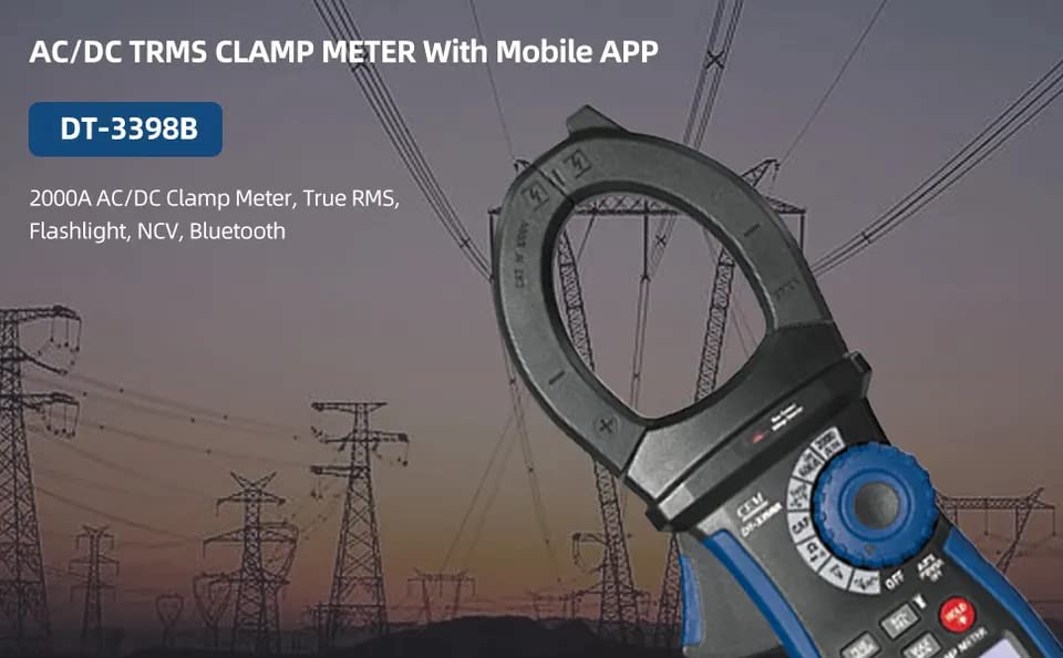
Figure 2: The DT-3398B Clamp Meter, illustrating its capability for AC/DC TRMS measurement and mobile app integration via Bluetooth.
4. Setup
4.1 Battery Installation
The DT-3398B requires one 9V battery for operation. To install or replace the battery:
- Ensure the meter is powered off and disconnected from all circuits.
- Locate the battery compartment cover on the rear of the meter.
- Use a screwdriver to loosen the screw(s) securing the cover.
- Remove the cover and insert a new 9V battery, observing correct polarity.
- Replace the cover and tighten the screw(s).
4.2 Connecting Test Leads
For voltage, resistance, capacitance, and diode measurements, connect the test leads to the input jacks:
- Insert the black test lead into the COM (Common) jack.
- Insert the red test lead into the VΩCAPHzTemp jack.

Figure 3: User holding the DT-3398B Clamp Meter, demonstrating proper grip and test lead connection points.
5. Operating Instructions
This section details the operation of various functions of the DT-3398B clamp meter.
5.1 Power On/Off and Function Selection
- To power on the meter, rotate the central rotary dial from the OFF position to the desired measurement function.
- To power off, rotate the dial back to the OFF position.
- The meter features an Auto Power Off function to conserve battery life. It will automatically shut down after a period of inactivity.
5.2 AC/DC Current Measurement (Clamp Jaw)
- Rotate the dial to the A~ (AC Current) or A= (DC Current) position.
- Press the jaw trigger to open the clamp jaw.
- Encircle a single conductor with the clamp jaw. Ensure the jaw is fully closed.
- Read the current value on the LCD display.
- For DC current, use the DCA Zero function (if available via a button) to zero the display before measurement to eliminate residual magnetism effects.
5.3 AC/DC Voltage Measurement
- Rotate the dial to the V~ (AC Voltage) or V= (DC Voltage) position.
- Connect the black test lead to the COM jack and the red test lead to the VΩCAPHzTemp jack.
- Touch the test probes to the circuit points where voltage is to be measured.
- Read the voltage value on the LCD display.
5.4 Resistance, Continuity, Diode, and Capacitance Measurement
- Rotate the dial to the ΩCAP position.
- Connect the test leads as described in Section 4.2.
- Use the MODE button to cycle through Resistance (Ω), Continuity (buzzer icon), Diode (diode symbol), and Capacitance (CAP) functions.
- For resistance, connect probes across the component.
- For continuity, a beep indicates a continuous circuit.
- For diode test, connect probes across the diode.
- For capacitance, connect probes across the capacitor (ensure it is discharged).
5.5 NCV (Non-Contact Voltage) Detection
- Rotate the dial to the NCV position.
- Move the top of the meter near a conductor or outlet.
- The meter will emit an audible beep and/or visual indication (e.g., flashing LED) if AC voltage is detected.
5.6 Special Functions (HOLD, MAX/MIN, Inrush, Flashlight, Bluetooth)
- HOLD: Press the HOLD button to freeze the current reading on the display. Press again to release.
- MAX/MIN: In a measurement function, press the MAX/MIN button to enter MAX/MIN recording mode. The meter will display the maximum or minimum value recorded. Press again to cycle.
- Inrush: This function is typically activated by a dedicated button or a specific dial position. It measures the initial surge current when a device (like a motor) starts up.
- Flashlight: Press the flashlight button (if dedicated) or hold a specific function button to activate the built-in flashlight.
- Bluetooth: Activate Bluetooth on the meter (if a dedicated button exists) and pair with a compatible mobile device running the specified application for data logging and remote viewing. Refer to the mobile application's instructions for detailed usage.

Figure 4: The DT-3398B Clamp Meter in use, demonstrating its ability to measure current and highlighting advanced features such as Peak Hold and Inrush Current measurement.
6. Maintenance
6.1 Cleaning
Wipe the meter's case with a damp cloth and a mild detergent. Do not use abrasives or solvents. Ensure the meter is completely dry before use.
6.2 Battery Replacement
Refer to Section 4.1 for instructions on battery replacement. Replace the battery when the low battery indicator appears on the display to ensure accurate measurements.
6.3 Calibration
Periodic calibration by qualified personnel is recommended to ensure the meter maintains its accuracy over time. Contact CEM customer support for calibration services.
7. Troubleshooting
| Problem | Possible Cause | Solution |
|---|---|---|
| Meter does not power on. | Dead or incorrectly installed battery. | Replace the 9V battery, ensuring correct polarity. |
| Inaccurate readings. | Low battery, incorrect function selected, damaged test leads, external interference. | Replace battery, verify function, check test leads for damage, move away from strong electromagnetic fields. |
| "OL" or "OVER" displayed. | Measurement exceeds the meter's range. | Select a higher range if available, or ensure the measured value is within the meter's specifications. |
| No NCV detection. | No AC voltage present, or meter not close enough to the source. | Verify the presence of AC voltage with another method, ensure the meter's NCV sensor is close to the conductor. |
| Bluetooth connection issues. | Bluetooth not enabled on meter or mobile device, app issues, out of range. | Ensure Bluetooth is active on both devices, restart app, move closer to the meter. |
8. Specifications
The following table outlines the key technical specifications for the CEM DT-3398B Clamp Meter:
| Function | Max Range | Basic Accuracy | Max. Resolution |
|---|---|---|---|
| AC Current | 2000 A | ±(2.5%+5d) | 1A |
| DC Current | 2000 A | ±(2.5%+5d) | 1A |
| AC Voltage | 1000V | ±(0.8%+2d) | 0.1mV |
| DC Voltage | 1000V | ±(1.0%+4d) | 0.1mV |
| Resistance | 60MΩ | ±(1.0%+5d) | 0.1Ω |
| Capacitance | 10mF | ±(3.0%+5d) | 0.01nF |
| Electronic Frequency | 100KHz | ±(1.2%+3d) | 0.01kHz |
| Temperature | 1000°C/1832°F | ±(3.0%+5d) | 1°C/°F |
| Total Harmonic Distortion | 99.9% | 0.1% | ±(3%+10d) |
| Harmonic distortion measurement | 99.9% | 0.1% | ±(5%+10d) |
| Active Power | 999.9KW | A error x Vreading + Verror x Areading | * |
| Power Factor | -1.0 ~ 0.0 ~ 1.0 | ±(3%+1d) | * |
| Continuity check | Buzzer sounds at 50Ω | * | |
| Diode test | Test current <0.5mA Max 3V | * |
General Specifications:
- Display: 6000 counts LCD
- Jaw Opening: 2 inches (52mm)
- Power Supply: 9V Battery
- Dimensions (LxWxH): 308mm x 97mm x 47mm
- Weight: 732g
- Safety Rating: CAT IV 1000V
- Certificates: CE, ISO 9001, RoHS
- Accessories: Test leads, temperature probe (for 3398B/3398W), gift box with carrying case. (Note: 9V battery is required and typically included, contradicting some accessory lists.)
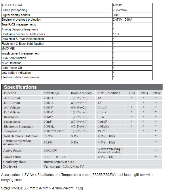
Figure 5: Detailed technical specifications for the DT-3398B Clamp Meter, including measurement ranges, accuracy, and resolution.
9. Warranty and Support
The manufacturer provides a 2-year availability for spare parts. For warranty claims, technical support, or service inquiries, please contact your local distributor or the manufacturer directly. Keep your purchase receipt as proof of purchase.


