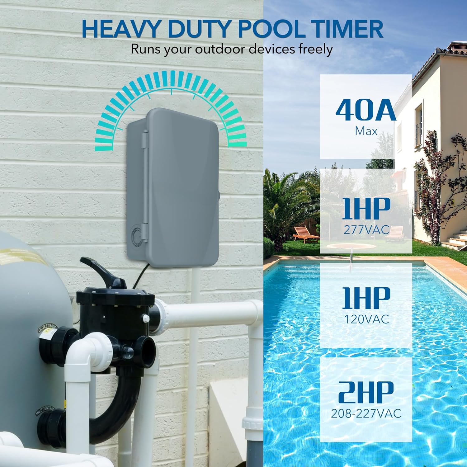
The BN-LINK Pool Pump Timer is a robust outdoor mechanical timer box engineered for heavy-duty applications. It provides precise 24-hour programmable control for various high-power electrical devices, including pool pumps, water heaters, fans, and spas. With a maximum capacity of 40A and compatibility with 120, 240, and 277 VAC, this timer is designed for reliability and durability in outdoor environments. It is ETL Listed, ensuring compliance with safety standards.
Important Safety Information
WARNING: To prevent electric shock, always ensure power is turned OFF at the circuit breaker before installation, servicing, or removing the insulating panel. Installation and wiring of this product should always be performed by a qualified electrician in accordance with all local and national electrical codes. Do not apply power to the timer until the DIP switch is correctly set for your input voltage.
Setup and Installation
Getting Started
Before beginning installation, open the front cover of the timer box. Carefully remove the protective inner panel to access the internal components and DIP switches.
Image: The BN-LINK Pool Pump Timer with its front cover open, revealing the internal wiring diagrams and the mechanical timer dial.
Setting the DIP Switch
The DIP switch must be set to the correct input voltage before applying power. Refer to the diagrams below and on the inner panel of the timer for proper configuration:
120 VAC: All four DIP switches (1, 2, 3, 4) should be in the 'ON' (up) position.
277 VAC: All four DIP switches (1, 2, 3, 4) should be in the 'OFF' (down) position.
Ensure the DIP switch setting matches your supply voltage to prevent damage to the unit.
Wiring Instructions
The timer supports various wiring configurations (SPDT and DPDT) to control one or two devices. Always turn off power at the circuit breaker before wiring. Refer to the detailed wiring diagrams provided on the inner panel of the timer and in the included guide for specific connections.
Image: Typical DPDT wiring diagrams for 120V, 208/240V, and 277V loads.
Image: Typical SPDT wiring diagrams for various loads and voltages, including two-speed fan wiring.
For a visual guide on wiring, please watch the official installation video:
Video: Official BN-LINK installation guide for the Outdoor Mechanical Pool Pump Timer Box, demonstrating wiring steps.
Mounting
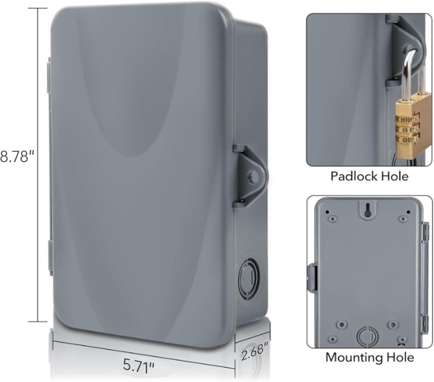
The timer box is designed for wall mounting. Use the provided external mounting tabs and screws to securely attach the unit to a suitable surface. Ensure the mounting location is stable and allows for proper access and ventilation.
Image: Product dimensions and details on the padlock hole and mounting holes for secure installation.
Operating Your Timer
Switch Operation
The timer features a manual switch with three positions: ON, OFF, and AUTO.
ON: When the switch is in the 'ON' position (down), the connected device will remain continuously powered, overriding any programmed settings.
OFF: When the switch is in the 'OFF' position (middle), the connected device will remain continuously off, overriding any programmed settings.
AUTO: When the switch is in the 'AUTO' position (up), the timer will follow the programmed ON/OFF schedules set on the dial.
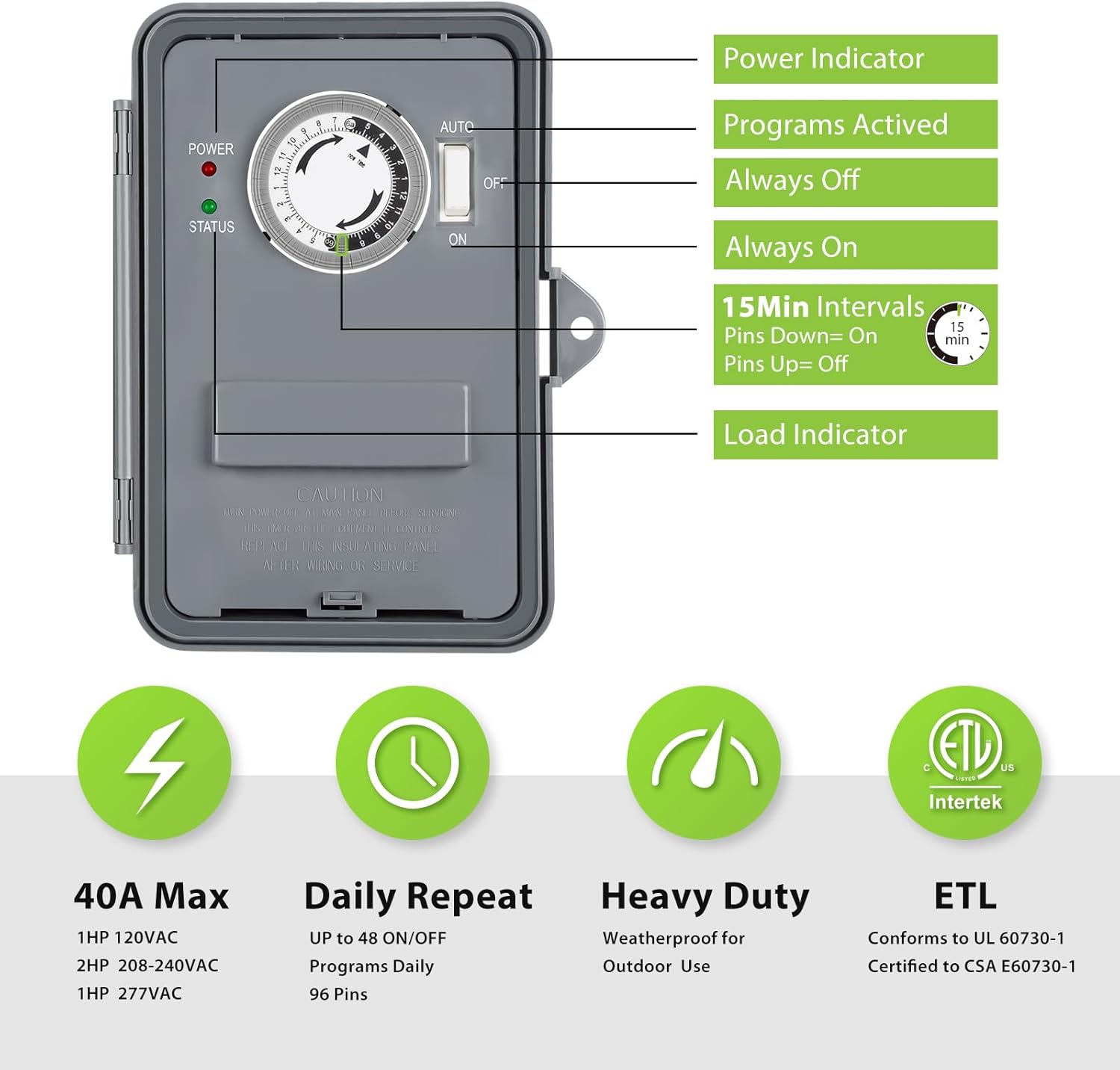
Image: The timer's control panel, highlighting the power indicator, activated programs, always off/on positions, 15-minute intervals, and load indicator.
Setting the Time
To set the current time, rotate the timer dial clockwise until the 'NOW TIME' arrow points to the current time of day. The white portion of the dial represents 6 AM to 6 PM, and the black portion represents 6 PM to 6 AM.
Image: The timer dial illustrating how to set specific ON times (e.g., 1:00 AM-3:00 AM, 8:00 AM-10:45 AM, 1:00 PM-2:15 PM, 5:30 PM-7:00 PM).
Setting Schedules
The timer dial has 96 small pins, each representing a 15-minute interval. To program an 'ON' period, push down the pins corresponding to the desired time frame. For 'OFF' periods, leave the pins in the 'UP' position. Ensure the manual switch is set to 'AUTO' for the programmed schedule to take effect.
In case of a power failure, the timer's current time setting may need to be reset manually once power is restored.
Image: A close-up of the timer dial, showing the 15-minute interval pins. Pins pushed down activate the load, while pins left up keep it off.
Product Specifications
Feature
Specification
Brand
BN-LINK
Model Number
U49
Voltage
120 to 277 VAC
Max Amperage
40A Resistive
Horsepower Capacity
1HP to 2HP
Program Cycles
24-Hour Daily Repeat
Minimum Interval
15 minutes (96 pins)
Material
Polycarbonate
Working Temperature
-40℉ to 130℉
Certifications
ETL Listed, Conforms to UL 60730-1, Certified to CSA E60730-1
Product Dimensions
2.71"D x 7.08"W x 8.86"H
Item Weight
1.72 pounds
Troubleshooting
If you encounter any technical problems during installation or operation, please refer to the detailed wiring diagrams and instructions provided on the inner panel of the timer box and in the included user guide. For further assistance, please contact BN-LINK customer service.
Warranty and Support
This BN-LINK product comes with a 12-month warranty. If you experience any issues or require technical support, please do not hesitate to contact our friendly customer service team. We are committed to providing professional help and will reply to your correspondence within 24 hours.
Related Documents - U49
BN-LINK CP-U191 Dual Outlet Outdoor Digital Timer User Manual Comprehensive guide for the BN-LINK CP-U191 Dual Outlet Outdoor Digital Timer, covering setup, programming, safety instructions, and troubleshooting. Features include dual outlets, weatherproof design, and energy-saving capabilities.
BN-LINK BNH-60/U92 12 Hour Mechanical Countdown Timer User Manual Comprehensive user manual for the BN-LINK BNH-60/U92 12-hour mechanical countdown timer. Includes setup instructions, applications, technical ratings, safety warnings, and troubleshooting guide.
BN-LINK BND-60/U97A Short Period Repeat Cycle Timer User Manual User manual for the BN-LINK BND-60/U97A Short Period Repeat Cycle Timer. This guide details product features, installation, optional settings for 24-hour, day, and night control, troubleshooting common issues, and warranty information.
BN-LINK BND-60/U47 24-Hour Mechanical Mini Timer User Manual User manual for the BN-LINK BND-60/U47 24-hour mechanical mini timer. Provides instructions on setting schedules, operating the device, and troubleshooting common issues for automated control of electrical devices.