1. Introduction
Thank you for choosing the MaxPow W88-C 30A PWM Solar Charge Controller. This device is designed to manage the power flow from your solar panels to your battery bank, ensuring efficient charging and protecting your batteries from overcharge and over-discharge. It features automatic 12V/24V voltage detection, an LCD display, and dual USB outputs for charging external devices.

Figure 1: Front view of the MaxPow W88-C Solar Charge Controller, showing the LCD display, control buttons, and USB ports.
2. Product Features
- Advanced PWM Charging: Utilizes 3-stage PWM charging management for optimal battery health.
- Automatic Voltage Detection: Automatically detects 12V or 24V system voltage.
- LCD Display: Provides clear visual indication of charging status and system parameters.
- Dual USB Outputs: Two 5V/2A USB ports for charging mobile devices.
- Built-in Timer: Programmable timer for load output control.
- Comprehensive Protections: Includes short-circuit, overload, over-discharge, and reverse polarity protection.

Figure 2: The MaxPow W88-C controller featuring two USB ports for convenient device charging.
3. Safety Precautions
Please read all instructions carefully before installation and operation. Failure to follow these instructions may result in damage to the unit, batteries, or other components, and may void the warranty.
- Ensure proper ventilation around the controller.
- Connect the controller to the battery first, then the solar panel, and finally the load. Disconnect in the reverse order.
- Use appropriate wire gauges for all connections to prevent overheating.
- Avoid short-circuiting the battery or solar panel terminals.
- Keep the controller away from water and corrosive environments.
- This controller is designed for lead-acid batteries (Gel, Sealed, Flooded, AGM). Do not use with other battery types unless specified.
4. Setup and Installation
4.1 Wiring Connections
Follow the connection order strictly to ensure proper operation and prevent damage. Connect the components in the following sequence:
- Connect the Battery: Connect the battery to the charge controller's battery terminals (middle terminals). Ensure correct polarity (+ to + and - to -). The LCD will display the battery voltage.
- Connect the Solar Panel: Connect the solar panel to the charge controller's solar panel terminals (left terminals). Ensure correct polarity.
- Connect the Load: Connect the DC load to the charge controller's load terminals (right terminals). Ensure correct polarity.
To disconnect the system, follow the reverse order: disconnect the load, then the solar panel, and finally the battery.

Figure 3: Wiring diagram showing connections for solar panels, battery, and DC load to the controller.
4.2 Battery Type Selection
The controller supports various lead-acid battery types. Refer to the technical specifications for default voltage settings for Gel, Sealed, and Flooded batteries. These settings are typically configurable through the controller's menu. Consult your battery manufacturer's specifications for optimal charging parameters.
5. Operating Instructions
5.1 LCD Display and Buttons
The LCD display shows real-time system status, including battery voltage, charging current, discharge current, and load status. The controller typically has three buttons for navigation and setting adjustments:
- Menu Button: Used to cycle through display screens and enter setting modes.
- Up Button: Used to increase values or navigate upwards in menus.
- Down Button: Used to decrease values or navigate downwards in menus.
Note: Specific button functions and menu navigation may vary slightly. Refer to the on-screen prompts for detailed operation.
5.2 USB Output
The two USB ports provide a 5V/2A output for charging compatible electronic devices. These ports are active when the controller is powered by the battery.
5.3 Load Control Timer
The controller includes a programmable timer for the DC load output. This allows you to set specific hours for the load to be active, conserving battery power when the load is not needed.
6. Protections
The MaxPow W88-C controller incorporates several protection mechanisms to ensure the safety and longevity of your solar power system:
- Short-Circuit Protection: Protects against damage from short circuits in the solar panel, battery, or load circuits.
- Overload Protection: Prevents damage if the connected load draws excessive current.
- Over-Discharge Protection: Disconnects the load when the battery voltage drops below a safe level, preventing deep discharge and extending battery life.
- Reverse Polarity Protection: Protects the controller and connected components from damage due to incorrect wiring of battery or solar panel polarity.
7. Technical Specifications
| Parameter | Value |
|---|---|
| Model | W88-C |
| Nominal System Voltage | 12V/24V Auto-detection |
| Rated Charge Current | 30A |
| Rated Discharge Current | 10A |
| Max. PV Input Voltage | 50V |
| Max. PV Input Power (12V System) | 390W |
| Max. PV Input Power (24V System) | 780W |
| USB Output | Dual 5V/2A (Max) |
| Self-Consumption | <10mA |
| Operating Temperature Range | -35°C to +60°C |
| Dimensions (L x W x H) | 135 x 70 x 35 mm |
| Weight | 290 Grams |
| Supported Battery Types | Gel, Sealed, Flooded, AGM |
| Float Voltage (Default) | 13.7V (Configurable) |
| Discharge Stop Voltage (Default) | 10.7V (Configurable) |
| Discharge Reconnect Voltage (Default) | 12.6V (Configurable) |
Note: All voltages for 24V systems are approximately double the 12V system values.
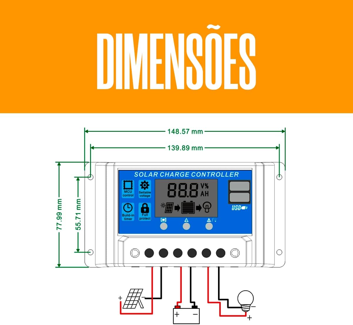
Figure 4: Dimensional drawing of the MaxPow W88-C controller.

Figure 5: Diagram illustrating maximum photovoltaic panel power input for 12V (390W) and 24V (780W) battery systems.
8. Maintenance
To ensure optimal performance and longevity of your solar charge controller, periodic maintenance is recommended:
- Clean Terminals: Periodically check and clean all wiring terminals to ensure tight connections and prevent corrosion.
- Inspect Wiring: Verify that all wires are securely connected and free from damage.
- Ventilation: Ensure the controller's ventilation openings are not obstructed to allow for proper heat dissipation.
- Environmental Check: Keep the controller in a dry, well-ventilated area, away from direct sunlight and extreme temperatures.
9. Troubleshooting
If you encounter issues with your MaxPow W88-C solar charge controller, refer to the following common problems and solutions:
- No Display/No Power:
- Check battery connections for correct polarity and secure contact.
- Ensure the battery voltage is above the minimum operating voltage (typically 8V-10V).
- Battery Not Charging:
- Verify solar panel connections and polarity.
- Check if the solar panel is receiving sufficient sunlight.
- Ensure the solar panel voltage is within the controller's operating range (Max. PV Input Voltage 50V).
- Inspect for any blown fuses in the solar panel circuit (if applicable).
- Load Not Working:
- Check load connections and polarity.
- Verify that the battery is sufficiently charged (not in over-discharge protection).
- Ensure the load current does not exceed the rated discharge current (10A).
- Check timer settings if the load is controlled by the timer function.
- USB Ports Not Charging:
- Ensure the controller is powered by the battery.
- Check the USB cable and the device being charged.
10. Warranty and Support
For warranty information and technical support, please refer to the documentation provided at the time of purchase or contact your retailer. Keep your purchase receipt as proof of purchase.
For further assistance, you may also visit the manufacturer's website or contact their customer service department. Please have your product model (W88-C) and purchase details ready when seeking support.


