1. Product Overview
The DINUY IT KNT 008 is a versatile mixed actuator designed for electrical installations, offering 8 channels for ON/OFF switching or 4 channels for controlling blinds/roller shutters. It is suitable for DIN rail mounting and integrates seamlessly into KNX systems.
Key Features:
- 8 ON/OFF switching channels or 4 blind/roller shutter channels.
- Maximum switching capacity of up to 16A per channel.
- 8 potential-free contacts.
- Modular format (8 modules wide) for DIN rail installation.
- Manual override push buttons on the front panel for each channel, independent of bus connection.
- 8 binary inputs + 4 binary/analog inputs.
- LED status indicators for each output channel and error situations.
- Supports various functions including timers, scenes, logical operations, and forced operation.

Figure 1: Front view of the DINUY IT KNT 008 actuator, showing manual override buttons, LED indicators, and connection terminals.
2. Safety Instructions
Please read these instructions carefully before installation and operation. Failure to follow these instructions may result in damage to the device, property, or personal injury.
- Installation must be performed by a qualified electrician in accordance with national wiring regulations.
- Disconnect power before installation, maintenance, or troubleshooting.
- Do not expose the device to moisture, extreme temperatures, or direct sunlight.
- Ensure proper grounding.
- Do not open or modify the device. There are no user-serviceable parts inside.
3. Installation and Setup
3.1 Mounting
The DINUY IT KNT 008 is designed for DIN rail mounting (EN 60715). It occupies 8 modules of space.
- Ensure the DIN rail is securely installed within a suitable electrical enclosure.
- Align the actuator with the DIN rail and press firmly until it clicks into place.

Figure 2: Technical drawing showing the dimensions (in mm) of the DINUY IT KNT 008 actuator, including front and side views. Dimensions are approximately 90mm (height), 70mm (width), and 60mm (depth).
3.2 Wiring
Refer to the wiring diagrams below and the labels on the device for correct connections. All connections should be made with appropriate cable sizes and insulation.
Power Supply: Connect L (Line) and N (Neutral) to the designated terminals.
Output Channels: The device provides 8 potential-free contacts. Each channel (A1/A2, B1/B2, C1/C2, D1/D2 for switching; or A1/A2, B1/B2 for roller shutters) can handle up to 16A.
Binary Inputs: The device has 8 binary inputs (5-12) and 4 binary/analog inputs (1-4). These inputs can be used for connecting push buttons, sensors, or other devices.
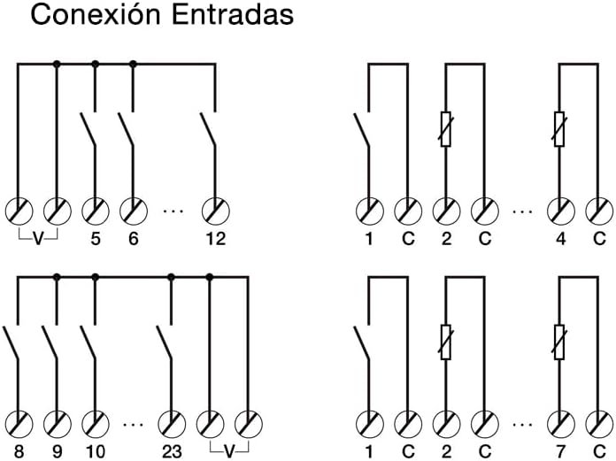
Figure 3: Wiring diagrams illustrating various input connection configurations for the DINUY IT KNT 008, including connections for binary inputs (5-12) and binary/analog inputs (1-4) with common voltage (V) or common (C) terminals.
KNX Bus Connection: Connect the KNX bus cable to the dedicated KNX terminals on the device.
3.3 Initial Commissioning
After physical installation and wiring, the device needs to be commissioned using ETS (Engineering Tool Software) version 5 or higher.
- Ensure the KNX bus is powered and connected to your ETS programming interface.
- Open ETS software and create a new project or open an existing one.
- Import the product database for the DINUY IT KNT 008 (if not already available).
- Add the device to your project topology.
- Assign a physical address to the device.
- Configure the desired parameters for each channel (e.g., ON/OFF switching, roller shutter control, timer functions, scene participation, logical operations).
- Download the configuration to the device.
- Test the functionality of all configured channels and inputs.
4. Operating the Device
4.1 Manual Operation
The DINUY IT KNT 008 features manual override buttons on its front panel for each channel. These buttons allow for local control of the outputs, independent of the KNX bus status.
- Press the "ON/OFF" button for a specific channel to toggle its state (for switching outputs).
- For roller shutter channels, the buttons typically control UP/DOWN movement.
- The LED indicators next to each button will show the current status of the output.
4.2 Automatic Operation (KNX)
Once commissioned via ETS, the device operates automatically based on the programmed logic and communication objects received via the KNX bus. This includes:
- Receiving switching commands from KNX push buttons, sensors, or other actuators.
- Executing timer functions.
- Participating in scene recalls.
- Performing logical operations based on input conditions.
- Responding to forced operation commands.
4.3 Status Indicators
The device is equipped with LEDs to indicate the status of each output channel and potential error situations.
- Channel LEDs: Typically illuminate when the corresponding output is active (e.g., ON for switching, UP/DOWN for roller shutters).
- Error LEDs: Indicate specific fault conditions. Refer to the ETS software for detailed error codes and troubleshooting steps if an error LED is active.
- KNX LED: Indicates KNX bus communication status.
5. Maintenance
The DINUY IT KNT 008 is a low-maintenance device. No regular maintenance is required beyond ensuring proper ventilation and keeping the device free from dust and debris.
- Before cleaning, disconnect power to the device.
- Use a soft, dry cloth to wipe the exterior. Do not use liquid cleaners or solvents.
- Periodically check wiring connections for tightness, especially after initial installation.
6. Troubleshooting
If you encounter issues with your DINUY IT KNT 008, refer to the following common problems and solutions:
| Problem | Possible Cause | Solution |
|---|---|---|
| Device not responding to KNX commands. | No KNX bus voltage; Incorrect physical address; Configuration error; Bus cable disconnected. | Check KNX bus power supply; Verify physical address in ETS; Re-download configuration; Check bus cable connection. |
| Output channel not switching. | No power supply to the device; Incorrect wiring of the load; Overload on the channel; Internal fault. | Check L/N connections; Verify load wiring; Check load current against specifications (max 16A); Contact support if internal fault suspected. |
| Manual override buttons not working. | Device not powered; Internal fault. | Ensure power supply is connected; If power is present, contact support. |
| Error LED is active. | System error; Overload; Short circuit. | Consult ETS software for specific error details; Check for overloads or short circuits on outputs; Cycle power to the device. |
If the problem persists after attempting these solutions, please contact Dinuy technical support.
7. Specifications
| Parameter | Value |
|---|---|
| Model | IT KNT 008 |
| Brand | Dinuy |
| Channels | 8 (ON/OFF) or 4 (Blinds/Roller Shutters) |
| Switching Capacity per Channel | Max. 16A |
| Contacts | 8 potential-free contacts |
| Inputs | 8 Binary + 4 Binary/Analog |
| Mounting | DIN Rail (8 modules wide) |
| Programming | ETS5 or higher |
| Dimensions (approx.) | 90mm (H) x 70mm (W) x 60mm (D) |
| ASIN | B0BVCS9MCG |
8. Warranty and Support
8.1 Warranty Information
Dinuy products are manufactured to high quality standards. For specific warranty terms and conditions, please refer to the warranty documentation provided with your purchase or visit the official Dinuy website. Keep your proof of purchase for warranty claims.
8.2 Technical Support
For technical assistance, installation queries, or troubleshooting beyond the scope of this manual, please contact Dinuy technical support. You can typically find contact information on the official Dinuy website or through your local distributor.
When contacting support, please have the following information ready:
- Product Model: IT KNT 008
- Description of the issue
- Steps already taken to resolve the issue
- Purchase date and location


