
1. Introduction
This manual provides essential information for the safe and efficient operation of your QNK 1.5KW 2HP 110V AC Variable Frequency Drive (VFD) Converter. This device is designed to convert single-phase 110V AC power to three-phase 110V AC, enabling precise speed control for various industrial motors, including those used in CNC applications.

Image 1.1: Overview of the QNK 1.5KW VFD Converter.
2. Safety Information
Please read all safety instructions carefully before installation, operation, or maintenance of the VFD. Failure to comply with these instructions may result in personal injury or equipment damage.
2.1 General Safety Precautions
- Ensure all power is disconnected before performing any wiring or maintenance.
- Only qualified personnel should install and service this equipment.
- Protect the VFD from moisture, dust, and corrosive gases.
- Ensure proper grounding of the VFD and connected motor.
- Do not touch internal components immediately after power-off, as residual voltage may be present.
2.2 VFD Specific Warnings
- The VFD cannot be used as a power source for other equipment.
- Do not use the VFD to drive a motor with a supply voltage lower than 80V.
- Do not connect the VFD’s output terminals with capacitive loads.
- For heavy equipment like cranes or compressors, choose a VFD with a larger power output than the motor (e.g., a 7.5 Kw VFD for a 5.5 Kw motor).
- If a generator is used to power the VFD, ensure the generator's output voltage level is within +/-15% of the VFD's rated input.
3. Product Overview
3.1 Key Features
- Power Specifications: Input: 1-phase 110 VAC (+/- 15%), 0-14 A, 50/60 Hz. Output: 3-phase 110 VAC, 0-7A, 0-1,000 Hz.
- Low-Noise Operation: Utilizes PWM control technology for reduced operational noise and electromagnetic interference.
- Control Modes: Supports V/F Control and Vector Control. Frequency setting modes include digital, analog, serial communication (RS485 MODBUS), and PID control.
- Enhanced Safety & Durability: Features protective functions against overload, fuse failure, over/under voltage, restart, stall, short circuit, and overheating. Constructed with copper coil internals and a nonflammable exterior for longevity and safety.
- Efficient Heat Dissipation: Multi-grid design provides ample cooling space between electronic components and the case.
- Wide Application: Suitable for various equipment such as Spindle Motors, CNC Routers, Milling Machines, Pumps, Compressors, and Grinders.
3.2 Product Dimensions

Image 3.1: The VFD measures approximately 15cm (5.9 inches) in height, 9cm (3.5 inches) in width, and 11.8cm (4.6 inches) in depth.
4. Setup and Installation
4.1 Component Identification
The QNK VFD features a detachable control panel for flexible installation and operation. An extension cable is included for remote mounting of the control panel.

Image 4.1: The VFD with its detachable control panel, which can be mounted separately using the provided extension cable.
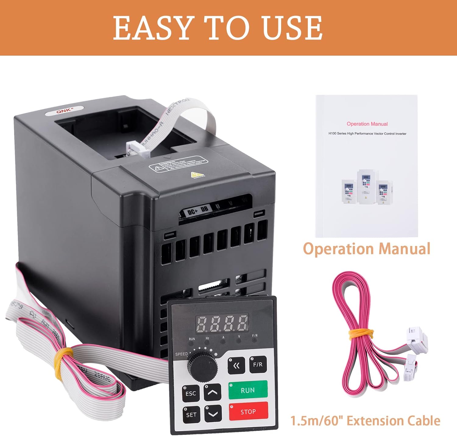
Image 4.2: The QNK VFD package includes the main unit, an operation manual, and a 1.5m (60-inch) extension cable for the control panel.
4.2 Wiring Diagram
Refer to the following diagram for proper electrical connections. Ensure all connections are secure and comply with local electrical codes.

Image 4.3: Detailed wiring diagram for the VFD, showing connections for power input, motor output, brake resistor, multi-function digital and analog inputs, and RS485 communication interface.
- Power Input (L1/L2/N): Connect your single-phase 110V AC power supply here. For three-phase AC380V, connect L1, L2, L3.
- Motor Output (U/V/W): Connect the three-phase motor leads to these terminals.
- Brake Resistor (DC+/DB): Optional connection for an external brake resistor to dissipate regenerative energy.
- Multi-function Digital Input (X1-X6/Y1F0): For external control signals.
- Multi-function Analog Output (AO/GND): For analog signal output.
- RS485 Communication Interface (485+/485-): For serial communication using the MODBUS protocol.
- Ground (PE/GND): Essential for safety. Ensure proper grounding.
5. Operating Instructions
5.1 Control Panel Functions
The VFD is operated via its intuitive control panel. Familiarize yourself with the buttons and their functions:

Image 5.1: The control panel with its buttons and a table describing each button's function.
| Button Icon | Button Name | Function Description |
|---|---|---|
| SET | SET | Go to the menu, or a certain parameter, and confirm the parameter. |
| ESC | ESC | Return to the previous menu or cancel an operation. |
| UP Arrow | UP | Modify and select parameters (increase value). |
| DOWN Arrow | DOWN | Modify and select parameters (decrease value). |
| Left/Right Arrows | SHIFT | Monitor different operation statuses and switch digit place during parameter setting. |
| F/R | F/R | Change the running direction of the motor (Forward/Reverse). |
| RUN | RUN | Initiate the motor operation. |
| STOP | STOP | Stop the motor operation or reset abnormal conditions. |
5.2 Frequency Setting Modes
The VFD supports various methods for setting the output frequency:
- Digital Setting: Adjust frequency directly using the control panel buttons.
- Analog Setting: Control frequency via an external analog signal (e.g., 0-10V or 4-20mA).
- Serial Communication Setting: Utilize the RS485 communication port with the standard international MODBUS protocol for remote control.
- PID Setting: Advanced calculus PID closed-loop arithmetic for precise and responsive control based on feedback.
5.3 Basic Operation Steps
- Power On: Connect the VFD to the appropriate power supply as per the wiring diagram.
- Set Parameters: Use the SET, UP, DOWN, and SHIFT buttons to configure necessary parameters (e.g., motor parameters, maximum frequency, acceleration/deceleration times). Refer to the detailed parameter list in the full manual for specific settings.
- Start Motor: Press the RUN button to start the motor.
- Adjust Frequency: Use the UP/DOWN arrows or the speed knob (if available) to adjust the output frequency and motor speed.
- Change Direction: Press the F/R button to switch the motor's rotation direction.
- Stop Motor: Press the STOP button to halt the motor.
6. Maintenance
Regular maintenance ensures the longevity and optimal performance of your VFD.
- Cleaning: Periodically clean the VFD's exterior to prevent dust accumulation, especially around ventilation openings. Use a soft, dry cloth. Do not use liquid cleaners.
- Ventilation: Ensure the VFD has adequate clearance for airflow. The powerful cooling fan and multi-grid design are crucial for heat dissipation. Blocked vents can lead to overheating.
- Wiring Inspection: Regularly check all electrical connections for tightness and signs of wear or damage. Loose connections can cause intermittent operation or electrical hazards.
- Environmental Conditions: Maintain the VFD in a clean, dry environment within its specified operating temperature and humidity ranges.

Image 6.1: The VFD features a powerful cooling fan and multiple capacitors for stable and durable operation, emphasizing the importance of proper ventilation.
7. Troubleshooting
The QNK VFD is equipped with multiple protective functions to ensure safe operation. If an error occurs, the VFD will typically display an error code or stop operation. Consult the full manual for specific error code interpretations.
7.1 Protective Functions

Image 7.1: The VFD includes comprehensive protection features such as overload, overheat, over-voltage, low-voltage, fuse, stall, short circuit, and reset protection.
- Overload Protection: Activates if the motor or VFD is subjected to excessive load.
- Fuse Protection: Indicates a blown fuse, often due to overcurrent.
- Over Voltage Protection: Triggers if DC bus voltage exceeds 400V.
- Under Voltage Protection: Triggers if DC bus voltage drops below 200V.
- Restart Protection: Prevents automatic restart after a fault without user intervention.
- Stall Protection: Detects if the motor is unable to rotate due to excessive load.
- Short Circuit Protection: Protects against short circuits in the output wiring.
- Overheat Protection: Activates if the VFD's internal temperature exceeds safe limits.
7.2 General Troubleshooting Steps
- Check Power Supply: Verify that the input voltage is stable and within the specified range.
- Inspect Wiring: Ensure all connections (input, output, control) are correct and secure.
- Review Parameters: Confirm that all VFD parameters are set correctly for your motor and application.
- Reduce Load: If an overload or stall fault occurs, reduce the mechanical load on the motor.
- Ensure Cooling: Check for obstructions around the VFD's ventilation openings and ensure the cooling fan is operating.
- Reset: After addressing the cause of a fault, press the STOP button to reset the VFD.
- Professional Assistance: If problems persist, contact QNK Customer Support or a qualified electrician.
8. Specifications
Detailed technical specifications for the QNK 1.5KW VFD Converter:
| Specification | Value |
|---|---|
| Product Dimensions | 8.89 x 11.68 x 14.99 cm |
| Weight | 1.31 kg |
| Input Voltage | 1-phase 110 VAC (+/- 15%) |
| Input Current | 0-14 A |
| Input Frequency | 50/60 Hz |
| Output Voltage | 3-phase 110 VAC |
| Output Current | 0-7A |
| Output Frequency | 0-1,000 Hz |
| Power Rating | 1.5KW (2HP) |
| Material | Copper (internals), ABS Flame Retardant (case) |
| Display Type | LED or LCD |
| Model Number | QNK-1.5KW |
| UPC | 729162004809 |
9. Warranty
The QNK 1.5KW 2HP 110V AC VFD Converter is covered by a standard manufacturer's warranty. For specific details regarding warranty duration, coverage, and claims process, please refer to the warranty card included with your product or contact QNK Customer Support.
10. Customer Support
Should you have any questions, require technical assistance, or need to report an issue with your QNK VFD Converter, please do not hesitate to contact our customer support team. We are committed to providing prompt and helpful service, typically responding within 24 hours.
For support, please visit the official QNK store on Amazon or use the contact information provided in your product packaging.
