
1. Product Overview
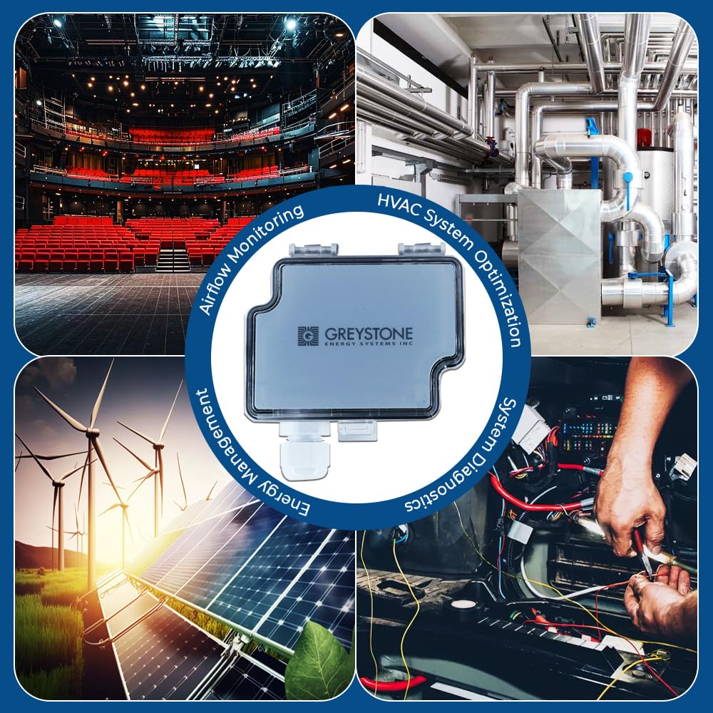
The Greystone AVDT-XX series of air velocity transmitters is specifically engineered for building automation systems within the HVAC/R industry. This device accurately measures both air velocity and temperature, offering field-selectable ranges and output options to suit various commercial environments.
Designed with a robust duct mount probe and an adjustable collar, it is suitable for installation in both round and rectangular ducts. Optional features include a relay output and a backlit LCD display, available in Metric or Imperial measurements.

2. Safety Information
Please read and understand all instructions before installing or operating the device. Failure to follow these instructions may result in equipment damage, property damage, or personal injury.
- Installation and servicing must be performed by qualified personnel only.
- Disconnect power before installation or maintenance to prevent electrical shock.
- Ensure wiring complies with all local and national electrical codes.
- Do not exceed the specified power supply voltage or current ratings.
- Avoid exposing the device to corrosive gases or liquids.
- Handle the sensor probe with care to prevent bending or damage.
3. Product Features
- Output: 2-wire loop-powered output.
- Accuracy and Reliability: Designed for precise and consistent measurements.
- Sensor Type: Electrochemical Sensor with Diffusion Method.
- Device Type: Three-Wire Device.
- Display: Optional 4-digit backlit display for clear readings.
- Enclosure: Durable ABS, Polycarbonate, IP54 (NEMA 3) rated.
- Adjustable Probe: Duct mount probe with adjustable collar for versatile installation.
4. Setup and Installation
Proper installation is crucial for accurate performance of the AVDT-XX sensor. Follow these steps carefully.
4.1. Unpacking and Inspection
Upon receiving the unit, inspect it for any signs of shipping damage. If damage is found, contact your supplier immediately. Ensure all components listed in the packing slip are present.
4.2. Mounting
The AVDT-XX sensor is designed for flange mounting in ducts. Select a location in the duct that provides a representative airflow sample, away from bends, dampers, or other obstructions that could cause turbulence.
- Drill a hole in the duct appropriate for the sensor probe (OD 10mm / 0.394”).
- Insert the probe into the duct to the desired depth. The adjustable collar allows for flexible positioning.
- Secure the mounting flange to the duct using appropriate fasteners through the Ø4mm (11/64”) holes. Ensure a tight seal to prevent air leakage.

4.3. Wiring
The AVDT-XX operates on a 24 Vdc / 24 Vac ±10% power supply. Refer to the internal wiring diagram for correct connections. Disconnect all power before wiring.


Power Supply: Connect 24 Vdc or 24 Vac to the designated power terminals. Observe polarity for DC connections.
Output Wiring: The sensor provides a 2-wire loop-powered output. Connect the output terminals to your building automation system (BAS) or controller as per its specifications. The device supports both current (mA) and voltage (V) output options, which are field-selectable.
Relay Output (Optional): If your model includes a relay, connect the NO (Normally Open), NC (Normally Closed), and COM (Common) terminals as required for your application. The relay has an adjustable switching point and hysteresis.
4.4. Field Selectable Settings
The AVDT-XX allows for field selection of velocity ranges and output types (current or voltage). Refer to the internal diagram (Figure 4) for jumper or switch settings. Ensure settings match your application requirements before powering on the device.
5. Operating Instructions
Once installed and wired, the AVDT-XX sensor operates continuously to provide air velocity and temperature data.
5.1. Power Up
Apply power to the device. The optional backlit LCD display will illuminate and show current readings after a brief initialization period.
5.2. Reading the Display (Optional LCD Model)
The 4-digit backlit display shows real-time air velocity and temperature measurements. The display may cycle between these values or show one at a time, depending on configuration. Units (Metric or Imperial) will be indicated on the display.
5.3. Data Output
The sensor continuously transmits measured data via its analog output (current or voltage) to the connected building automation system or controller. Refer to your BAS documentation for integrating and interpreting these signals.
5.4. Relay Function (Optional)
If equipped with a relay, it will activate or deactivate based on the configured setpoint for air velocity. This can be used to trigger alarms, control fans, or other HVAC components.
6. Maintenance
The Greystone AVDT-XX sensor is designed for minimal maintenance. However, periodic checks can ensure optimal performance.
- Cleaning: Periodically inspect the sensor probe for dust or debris accumulation. Gently clean the probe with a soft, dry cloth. Do not use abrasive cleaners or solvents.
- Connections: Annually check all electrical connections for tightness and signs of corrosion.
- Calibration: While the sensor is factory calibrated, if accuracy concerns arise, consult a qualified technician for recalibration or verification.
7. Troubleshooting
If the sensor is not performing as expected, review the following common issues and solutions before contacting support.
| Problem | Possible Cause | Solution |
|---|---|---|
| No display/No power | No power supply; Incorrect wiring; Blown fuse (external) | Verify power supply (24 Vdc/Vac); Check wiring connections; Inspect external fuses. |
| Inaccurate readings | Sensor probe dirty; Incorrect field settings; Turbulent airflow at sensor location; Sensor damage | Clean sensor probe; Verify field-selectable range and output settings; Relocate sensor to a stable airflow area; Contact support if damage is suspected. |
| No output signal | Incorrect wiring; BAS/controller input issue; Sensor malfunction | Check output wiring to BAS; Verify BAS input configuration; Test sensor output with a multimeter; Contact support if sensor malfunction is suspected. |
| Relay not activating | Incorrect setpoint; Wiring error; Relay malfunction | Adjust relay setpoint and hysteresis; Check relay wiring (NO/NC/COM); Contact support if relay malfunction is suspected. |
8. Specifications
| Parameter | Value |
|---|---|
| Model No. | CMD5B1100 |
| Media Compatibility | Dry air or non-aggressive gases |
| Velocity Ranges (Base & Metric) | 0-2, 10 & 20 m/s |
| Velocity Ranges (Imperial) | 0-400, 2000 & 4000 fpm |
| Thermal Shift | ±0.8 %FS / °C |
| Temperature Range | 0 to 50°C (32 to 122°F) |
| Temperature Accuracy | <0.5°C for velocity >0.5 m/s (<0.9°F for v > 100 fpm) |
| Operating Temperature | 0 to 50°C (32 to 122°F), 0 to 95 %RH, non-condensing |
| Storage Temperature | -20 to 70°C (-4 to 158°F) |
| Relay Output | 250 Vac, 6A / 30 Vdc, 6A (adjustable switching point and hysteresis) |
| Power Supply | 24 Vdc / 24 Vac ±10% |
| Current Consumption (Current Output) | 75 mA (90 mA with relay) |
| Current Consumption (Voltage Output) | 35 mA (50 mA with relay) |
| Display | 4 digit backlit display (45.7mm W x 12.7mm H) |
| Enclosure Material | ABS, Polycarbonate, IP54 (NEMA 3) |
| Case Dimensions (W x H x D) | 90mm x 71.5mm x 36mm (3.5” x 2.8” x 1.4”) |
| Probe Dimensions (OD x Length) | 10mm (0.394”) OD, 210mm (8.26”) length from bottom of cover |
| Mounting Flange | Ø4mm (11/64”) |
| Weight | 220g (7.76oz) |
| Mounting Type | Flange Mount |
9. Warranty and Support
9.1. Warranty Information
For detailed warranty terms and conditions, please refer to the documentation provided with your purchase or contact Ace Instruments directly. Keep your proof of purchase for warranty claims.
9.2. Technical Support
If you require further assistance with installation, operation, or troubleshooting that is not covered in this manual, please contact Ace Instruments technical support.
Manufacturer: Ace Instruments
Contact Number: 8142350506