

1. Introduction
This manual provides comprehensive instructions for the setup, operation, and maintenance of your VIHELM DSO150 Digital Oscilloscope. Please read this manual thoroughly before using the device to ensure proper functionality and to maximize its capabilities.
Key Features:
- ARM Cortex-M3 processor (STM32F103C8) for efficient performance.
- 2.4-inch color TFT display screen for clear waveform visualization.
- Supports Auto, Normal, and Single trigger modes for versatile waveform capture.
- Rising or falling edge trigger capability.
- Waveform parameter digital display including frequency, period, duty ratio, MAX/MIN/AVG/Peak-Peak/virtual values.
- HOLD function to freeze waveform display.
- Short-circuit and open-circuit detection for troubleshooting.
2. What's in the Box
Upon unpacking, please verify that all items listed below are present and in good condition:
- DSO150 Digital Oscilloscope Unit (x1)
- Oscilloscope Probe (x1)

Included oscilloscope probe with BNC connector and accessories.
3. Product Overview
Familiarize yourself with the various components and controls of the DSO150 oscilloscope.
Front Panel:

Angled view of the DSO150, highlighting the display and control buttons.
- Display Screen: 2.4-inch color TFT display for waveform visualization and parameter readings.
- V/DIV Button: Adjusts the vertical scale (volts per division).
- SEC/DIV Button: Adjusts the horizontal scale (time per division).
- TRIGGER Button: Cycles through trigger modes (Auto, Normal, Single).
- OK Button: Confirms selections or enters menus.
- ADJ Knob: Rotary encoder for fine adjustments of parameters.
Rear and Side Panels:

Rear view showing the AC/DC/GND coupling switch, 1KHz test signal output, and BNC input connector.
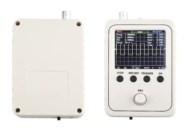
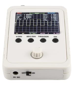
Side view indicating the 9V DC power input and ON/OFF switch.
The rear panel features the BNC input connector for the probe, a switch for AC/DC/GND coupling, and a 1KHz test signal output. The side panel includes the DC 9V power input and the main power switch.
4. Setup
- Power Connection: Connect a DC 9V (8-10V) power adapter to the DC 9V input port on the side of the oscilloscope.
- Probe Connection: Attach the oscilloscope probe to the BNC input connector on the rear panel. Ensure a secure connection.
- Power On: Flip the ON/OFF switch on the side panel to the "ON" position. The device display should illuminate.
- Probe Compensation (Optional but Recommended): If your probe has a compensation adjustment, connect the probe to the 1KHz test signal output. Adjust the probe's compensation until a clear, stable square wave is displayed on the screen.
5. Operating Instructions
This section details the basic operation of the DSO150 oscilloscope.
5.1. Basic Controls
- V/DIV: Press to cycle through vertical voltage scales (e.g., 5mV/div, 10mV/div, etc.).
- SEC/DIV: Press to cycle through horizontal time scales (e.g., 500s/div, 10us/div, etc.).
- ADJ Knob: Rotate to fine-tune parameters such as trigger level, position, or other selected settings. Press the knob to select or confirm.
- AC/DC/GND Switch: Located on the rear panel.
- AC: Blocks DC components, showing only the AC portion of the signal.
- DC: Displays both AC and DC components of the signal.
- GND: Disconnects the input signal and grounds the input, useful for setting the zero reference level.
5.2. Triggering
The trigger function stabilizes repetitive waveforms and captures single-shot events.
- TRIGGER Button: Press to switch between trigger modes:
- Auto: Triggers automatically, even without a stable signal.
- Normal: Triggers only when the signal meets the trigger conditions. If no trigger occurs, the display will not update.
- Single: Captures a single waveform when trigger conditions are met and then stops.
- Trigger Level: Use the ADJ knob to adjust the trigger level, which is the voltage point at which the oscilloscope starts acquiring data.
- Edge Trigger: The device supports rising or falling edge triggering. This setting is typically adjusted via the ADJ knob when the trigger function is active.
5.3. Waveform Analysis

The oscilloscope display showing multiple waveforms and digital parameter readouts like frequency, period, and voltage values.
- Digital Parameter Display: The screen displays various waveform parameters such as Frequency (Freq), Period (Cycl), Duty Cycle (Duty), Maximum Voltage (Umax), Minimum Voltage (Umin), Average Voltage (Uavg), Peak-to-Peak Voltage (Upp), and RMS Voltage (Urms).
- HOLD Function: Press the OK button (or a designated HOLD button if available) to freeze the current waveform display for detailed analysis.
- Negative Delay: Observe the waveform before the trigger point, which is useful for analyzing pre-trigger events.
6. Maintenance
- Cleaning: Use a soft, dry cloth to clean the device. Do not use abrasive cleaners or solvents.
- Storage: Store the oscilloscope in a dry, dust-free environment away from direct sunlight and extreme temperatures.
- Probe Care: Handle the probe carefully. Avoid bending or stressing the cable and connector.
7. Troubleshooting
- No Display/Power: Ensure the power adapter is correctly connected and the ON/OFF switch is in the "ON" position. Verify the power adapter is supplying 9V DC.
- No Waveform: Check the probe connection to both the oscilloscope and the circuit under test. Ensure the AC/DC/GND switch is set appropriately (usually DC or AC). Adjust V/DIV and SEC/DIV settings.
- Unstable Waveform: Adjust the trigger level and trigger mode (try Auto first, then Normal). Ensure the probe compensation is correctly set.
- Soldering Errors: The DSO150 features short-circuit and open-circuit detection, which can assist in identifying common soldering faults on PCBs. Refer to the device's specific menu options for this function.
8. Specifications
Detailed technical specifications for the VIHELM DSO150 Digital Oscilloscope:
| Parameter | Value |
|---|---|
| Processor | ARM Cortex-M3 (STM32F103C8) |
| Display Screen | 2.4-inch Color TFT |
| Maximum Real-time Sampling Rate | 1MSa/s |
| Analog Bandwidth | 0-200KHz |
| Sensitivity Range | 5mV/div - 20mV/div |
| Maximum Input Voltage | 50Vpk (1x probe) |
| Input Impedance | 1M ohms / 20pF |
| Accuracy | 12 Bits |
| Record Length | 1024 points |
| Coupling Modes | DC / AC / GND |
| Time Base Range | 500s/Div - 10us/Div |
| Trigger Modes | Auto, Normal, Single |
| Trigger Position | Center of Buffer |
| Supply Voltage | DC 9V (8-10V) |
| Current Consumption | ~120mA @ 9V |
| Main Board Size | 94 x 65mm / 3.7 x 2.56in |
| Analog Board Size | 65 x 47mm / 2.56 x 1.85in |
| Screen Size | 52 x 40mm / 2 x 1.57in |
Physical dimensions of the DSO150 Digital Oscilloscope.
9. Warranty and Support
For warranty information and technical support, please refer to the documentation provided with your purchase or contact the manufacturer directly. Keep your purchase receipt as proof of purchase.