
Cryfokt NLQ4-125 4P 100A
Automatic Transfer Switch User Manual
Model: NLQ4-125 4P 100A
1. Introduction
This user manual provides detailed instructions for the installation, operation, and maintenance of the Cryfokt NLQ4-125 4P 100A Automatic Transfer Switch (ATS). This device is designed to automatically switch between two power sources, such as utility power and a generator or solar energy, ensuring continuous power supply to critical loads.
2. Safety Information
WARNING: Installation and maintenance should only be performed by qualified personnel. Failure to follow these instructions may result in electric shock, fire, or serious injury.
- Always disconnect all power sources before installation, maintenance, or troubleshooting.
- Ensure proper grounding of the device.
- Verify voltage and current ratings match your electrical system requirements.
- Do not operate the switch if it appears damaged.
- Keep children and unauthorized personnel away from the installation area.
3. Product Overview and Features
The NLQ4-125 4P 100A Automatic Transfer Switch is a robust and reliable solution for managing dual power inputs. It features a millisecond response level circuit design for rapid and seamless power transfer.

Figure 3.1: Front and top view of the NLQ4-125 4P 100A Automatic Transfer Switch, showing the main components and terminals.
- Model: NLQ4-125 4P 100A
- Rated Operational Voltage: 220V (AC)
- Rated Current: 100 Amps
- Frequency: 50Hz/60Hz
- Operation Mode: Automatic and Manual
- Protection Rating: IP68 (International Protection Rating)
- Designed for critical applications such as elevators, hospitals, monitoring rooms, workshops, and fire boxes.

Figure 3.2: The Automatic Transfer Switch is suitable for various critical applications, including elevators, hospitals, monitoring rooms, workshops, and fire boxes, ensuring continuous power supply.
4. Setup and Installation
Before proceeding with installation, ensure all safety precautions are observed. The ATS is designed for DIN rail mounting within an electrical enclosure.
- Pre-installation Check: Before installation, carefully check the integrity of the ATS unit for any physical damage.
- Mounting: Securely mount the ATS on a standard DIN rail in a suitable electrical panel.
- Wiring Connections:
- Connect "Normal Power A" (e.g., utility grid) to the designated input terminals.
- Connect "Reverse Power B" (e.g., generator or solar energy) to the designated input terminals.
- Connect the load to the output terminals.
- Ensure all connections are tight and secure to prevent loose contacts and overheating.
- Control Wiring: Connect the AC220V passive input/output control wires as per your system's requirements for automatic operation.
- Initial Test: After wiring, turn the ATS on or off using the operating handle to check the flexibility of the transmission and detect the normal and backup power load generation and disconnection conditions at each stage.

Figure 4.1: Close-up view of the wiring terminals on the ATS, indicating connections for Normal Power A, Reverse Power B, and AC220V passive input/output.
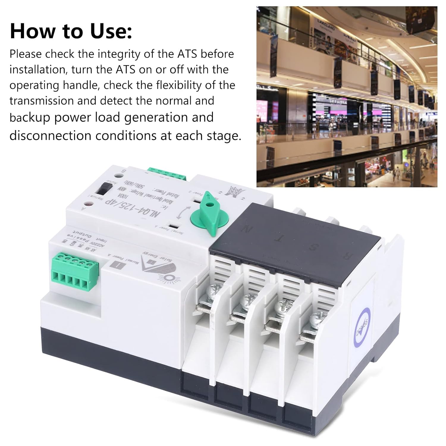
Figure 4.2: Detail of the manual/auto selector switch and indicator lights on the ATS, crucial for operation and testing.
5. Operation
The NLQ4-125 ATS supports both automatic and manual operation modes.
5.1 Automatic Mode
In automatic mode, the ATS will automatically detect the presence and quality of both power sources and switch to the preferred source (Normal Power A) when available. If Normal Power A fails, it will automatically switch to Reverse Power B. When Normal Power A is restored, the ATS will switch back to it.
- Set the selector switch to "Auto".
- Ensure both power sources are connected and active.
- The ATS will manage power transfer without manual intervention.
5.2 Manual Mode
Manual mode allows for direct control over which power source is active.
- Set the selector switch to "Manual".
- Use the operating handle to manually switch between "Normal Power A" and "Reverse Power B".
- This mode is useful for testing or specific operational requirements.
Video 5.1: Demonstration of the Dual Power Automatic Transfer Switch in operation, showing the automatic switching functionality between power sources.
6. Maintenance
Regular maintenance ensures the longevity and reliable operation of your ATS.
- Visual Inspection: Periodically inspect the ATS for any signs of damage, loose connections, or overheating.
- Cleaning: Keep the unit clean and free from dust and debris. Use a dry, soft cloth for cleaning. Do not use liquid cleaners.
- Terminal Check: Annually check all terminal connections for tightness.
- Functional Test: Periodically test the automatic transfer function by simulating a power outage on the primary source.
7. Troubleshooting
This section addresses common issues you might encounter with the ATS.
| Problem | Possible Cause | Solution |
|---|---|---|
| ATS does not switch automatically. |
|
|
| No power to load. |
|
|
| Overheating or burning smell. |
|
|
8. Specifications
| Parameter | Value |
|---|---|
| Model | NLQ4-125 4P 100A |
| Brand | Cryfokt |
| Operation Mode | Automatic |
| Current Rating | 100 Amps |
| Operating Voltage | 220 Volts |
| Frequency | 50Hz/60Hz |
| Connector Type | Auxiliary |
| International Protection Rating | IP68 |
| Connectivity Protocol | X-10 |
| Manufacturer | Cryfokt |
| Date First Available | December 15, 2024 |
9. Warranty and Support
Cryfokt products are manufactured to high-quality standards. For warranty information or technical support, please refer to the contact details provided with your purchase or visit the official Cryfokt website.
Online Support: Visit the Cryfokt Store on Amazon
Related documentsNLQ4-125 4P 100A


Ask a question about this manual
Ask about setup, troubleshooting, compatibility, parts, safety, or missing instructions. Manuals+ will review the question and use this page’s manual context to help answer it.