
VIHELM ZT111
VIHELM ZT111 Digital Multimeter
User Instruction Manual
1. Introduction
This manual provides comprehensive instructions for the safe and effective operation of your VIHELM ZT111 Digital Multimeter. Please read this manual thoroughly before using the device to ensure proper function and to prevent potential hazards. Keep this manual for future reference.
2. Safety Information
Warning: Improper use of this multimeter can cause damage, electric shock, or serious injury. Always observe all safety precautions.
- Always ensure the test leads are properly connected and the function switch is set to the correct range before making any measurements.
- Do not measure voltage exceeding the maximum rated input (DC 1000V, AC 750V).
- Exercise extreme caution when working with voltages above 60V DC or 30V AC RMS, as these pose a shock hazard.
- Before measuring current, ensure the circuit is de-energized and the multimeter is connected in series with the load.
- Replace batteries when the low battery indicator appears to ensure accurate readings.
- Do not operate the multimeter if it appears damaged or if the case is open.
- Always use the correct terminals, function, and range for measurements.
3. Product Overview
The VIHELM ZT111 is a compact, True RMS digital multimeter designed for measuring AC/DC voltage, AC/DC current, resistance, capacitance, frequency, temperature, diode, and continuity. It features a large LCD display, NCV (Non-Contact Voltage) detection, and an automatic/manual ranging function.
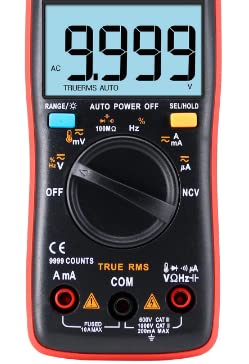
Figure 3.1: Front view of the ZT111 Digital Multimeter, showing the display, rotary switch, and input jacks.
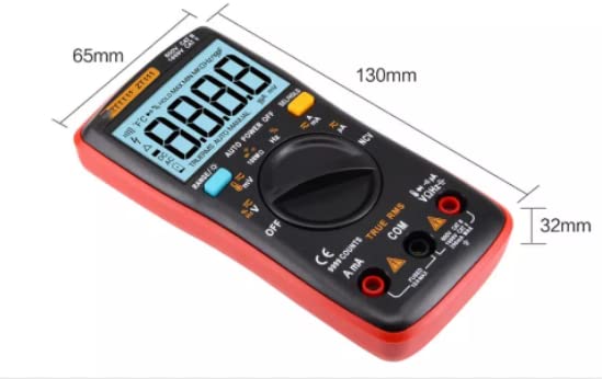
Figure 3.2: The ZT111 Digital Multimeter is designed for comfortable handheld use.
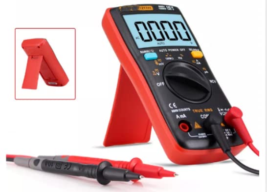
Figure 3.3: The ZT111 features an integrated kickstand for convenient hands-free operation.
3.1 Components
- LCD Display: Shows measurement readings, units, and function indicators.
- Rotary Switch: Selects the desired measurement function.
- Function Buttons: For range selection, data hold, backlight, and other features.
- Input Jacks: Terminals for connecting test leads (COM, VΩHz, mA, A).
4. Setup
4.1 Battery Installation
The ZT111 requires 2 AAA batteries (not included) for operation.
- Ensure the multimeter is turned OFF.
- Locate the battery compartment cover on the back of the device.
- Use a screwdriver to open the battery compartment.
- Insert two AAA batteries, observing the correct polarity (+/-) as indicated inside the compartment.
- Replace the battery compartment cover and secure it with the screw.
4.2 Connecting Test Leads
Always connect the black test lead to the 'COM' (Common) jack. Connect the red test lead to the appropriate input jack based on the measurement type:
- VΩHz: For voltage, resistance, frequency, capacitance, diode, and continuity measurements.
- mA: For milliampere current measurements.
- A: For ampere current measurements (up to 10A).
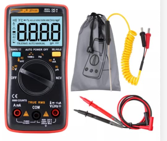
Figure 4.1: The ZT111 Multimeter comes with test leads and a temperature probe. Ensure leads are connected correctly for measurements.
5. Operating Modes
Turn the rotary switch to the desired function. The multimeter features automatic ranging for most functions, simplifying operation.
5.1 Voltage Measurement (AC/DC)
- Connect the red lead to the VΩHz jack and the black lead to the COM jack.
- Turn the rotary switch to the V~ (AC Voltage) or V- (DC Voltage) position.
- Connect the test probes in parallel to the circuit or component under test.
- Read the voltage value on the display.
5.2 Current Measurement (AC/DC)
Caution: Never connect the multimeter in parallel to a voltage source when measuring current, as this can damage the device and cause injury.
- Connect the black lead to the COM jack. Connect the red lead to the mA jack for small currents or the A jack for larger currents.
- Turn the rotary switch to the A~ (AC Current) or A- (DC Current) position.
- De-energize the circuit and open it at the point where current is to be measured.
- Connect the test probes in series with the circuit.
- Re-energize the circuit and read the current value.
5.3 Resistance Measurement
- Connect the red lead to the VΩHz jack and the black lead to the COM jack.
- Turn the rotary switch to the Ω position.
- Ensure the circuit or component is de-energized before measuring resistance.
- Connect the test probes across the component.
- Read the resistance value on the display.
5.4 Continuity Test
- Connect the red lead to the VΩHz jack and the black lead to the COM jack.
- Turn the rotary switch to the continuity symbol (speaker icon) position.
- Connect the test probes across the circuit or component.
- A continuous beep indicates a low resistance path (continuity).
5.5 Diode Test
- Connect the red lead to the VΩHz jack and the black lead to the COM jack.
- Turn the rotary switch to the diode symbol position.
- Connect the red probe to the anode and the black probe to the cathode of the diode.
- Read the forward voltage drop on the display. Reverse the probes; an open circuit reading indicates a good diode.
5.6 Capacitance Measurement
- Connect the red lead to the VΩHz jack and the black lead to the COM jack.
- Turn the rotary switch to the capacitance symbol position.
- Ensure the capacitor is fully discharged before testing.
- Connect the test probes across the capacitor.
- Read the capacitance value on the display.
5.7 Frequency Measurement
- Connect the red lead to the VΩHz jack and the black lead to the COM jack.
- Turn the rotary switch to the Hz position.
- Connect the test probes to the signal source.
- Read the frequency value on the display.
5.8 Temperature Measurement
- Connect the temperature probe to the VΩHz and COM jacks, observing polarity.
- Turn the rotary switch to the °C/°F position.
- Place the tip of the temperature probe on the object to be measured.
- Read the temperature value on the display.
5.9 Non-Contact Voltage (NCV) Detection
- Turn the rotary switch to the NCV position.
- Move the top end of the multimeter close to the conductor or outlet.
- The multimeter will emit an audible beep and the NCV indicator will light up if AC voltage is detected. The intensity of the beeps and lights increases with stronger voltage.
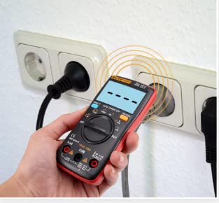
Figure 5.1: The NCV function allows for safe detection of AC voltage without direct contact.
5.10 Special Functions
- True RMS: Provides accurate measurements for non-sinusoidal AC waveforms.
- Data Retention (HOLD): Press the 'HOLD' button to freeze the current reading on the display. Press again to release.
- Backlight: Press the backlight button to illuminate the display for better visibility in low-light conditions.
- Automatic Shutdown: The multimeter will automatically power off after a period of inactivity to conserve battery life.
6. Maintenance
6.1 Cleaning
Wipe the case with a damp cloth and a mild detergent. Do not use abrasives or solvents. Ensure the device is completely dry before use.
6.2 Battery Replacement
When the low battery indicator appears on the display, replace the batteries as described in Section 4.1. Failure to do so may result in inaccurate readings.
6.3 Fuse Replacement
If the current measurement function fails, the fuse may need replacement. This operation should only be performed by qualified personnel. Refer to the specifications for the correct fuse type and rating.
7. Troubleshooting
- No Display: Check battery installation and ensure batteries are not depleted.
- Incorrect Readings: Verify test lead connections, ensure the correct function and range are selected, and check battery level.
- Current Measurement Not Working: Check the fuse. Ensure test leads are connected to the correct current jacks (mA or A).
- 'OL' on Display: Indicates an overload or out-of-range measurement. Select a higher range or ensure the component is not open-circuited.
8. Specifications
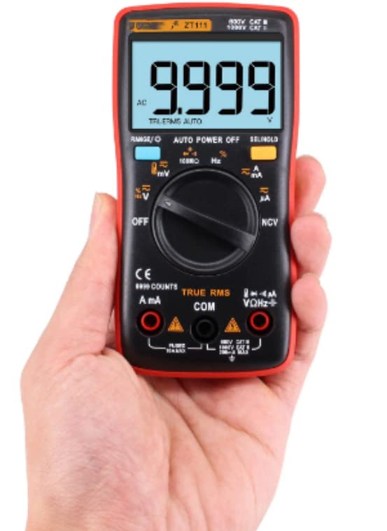
Figure 8.1: Physical dimensions of the ZT111 Digital Multimeter.
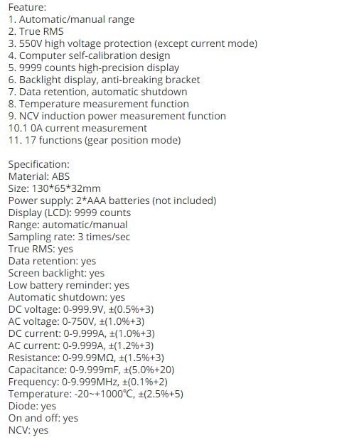
Figure 8.2: Detailed list of features and technical specifications.
| Parameter | Value |
|---|---|
| Material | ABS |
| Size (L x W x H) | 130 x 65 x 32 mm (5.12 x 2.56 x 1.26 inches) |
| Weight | 1 Kilogram (2.2 Pounds) |
| Power Supply | 2*AAA batteries (not included) |
| Display | LCD, 9999 counts |
| Sampling Rate | 3 times/sec |
| True RMS | Yes |
| Range | Automatic/Manual |
| Data Retention | Yes |
| Screen Backlight | Yes |
| Low Battery Reminder | Yes |
| Automatic Shutdown | Yes |
| High Voltage Protection | 550V (except current mode) |
| Safety Rating | 600V CAT III, 1000V CAT II |
| Function | Range | Accuracy |
|---|---|---|
| DC Voltage | 0-999.9V | ±(0.5%+3) |
| AC Voltage | 0-750V | ±(1.0%+3) |
| DC Current | 0-9.999A | ±(1.0%+3) |
| AC Current | 0-9.999A | ±(1.2%+3) |
| Resistance | 0-99.99MΩ | ±(1.5%+3) |
| Capacitance | 0-9.999mF | ±(5.0%+20) |
| Frequency | 0-9.999MHz | ±(0.1%+2) |
| Temperature | -20~+1000°C | ±(2.5%+5) |
| Diode | Yes | |
| On and Off (Continuity) | Yes | |
| NCV | Yes |
9. Warranty and Support
For warranty information or technical support regarding your VIHELM ZT111 Digital Multimeter, please contact the manufacturer or the seller directly. Refer to your purchase documentation for specific warranty terms and contact details. VIHELM is committed to providing customer support for its products.
Ask a question about this manual
Ask about setup, troubleshooting, compatibility, parts, safety, or missing instructions. Manuals+ will review the question and use this page’s manual context to help answer it.