
1. Introduction
This manual provides essential information for the safe and efficient operation of your Walfront Wind Solar Hybrid System Controller, model Walfrontw9574is816. This device is designed to manage power from both wind turbines and solar panels, ensuring optimal charging of 12V or 24V battery systems. It features MPPT (Maximum Power Point Tracking) technology for wind charging and PWM (Pulse Width Modulation) technology for solar charging, along with comprehensive protection mechanisms. Please read this manual thoroughly before installation and use.
2. Safety Instructions
- Electrical Safety: Always disconnect power sources (wind turbine, solar panels, battery) before installing or servicing the controller. High voltages can be present.
- Proper Wiring: Ensure all wiring is correctly sized and connections are secure to prevent overheating and damage. Observe correct polarity.
- Ventilation: Install the controller in a well-ventilated area to prevent overheating.
- Environment: Avoid installing the controller in direct sunlight, high humidity, or dusty environments.
- Battery Safety: Batteries can produce explosive gases. Ensure adequate ventilation when working near batteries. Wear eye protection.
- Professional Installation: If you are unsure about any part of the installation process, consult a qualified electrician or solar/wind power professional.
3. Product Overview
The Walfront Wind Solar Hybrid System Controller is designed to efficiently manage power input from both wind turbines and solar panels to charge a battery bank. It features a large LCD screen for easy monitoring and configuration.
Key Features:
- Hybrid Charging: Utilizes MPPT technology for wind turbine charging and PWM technology for solar panel charging.
- Automatic Voltage Identification: Automatically detects and adapts to 12V or 24V battery systems.
- Large LCD Screen: Displays real-time parameters such as voltage, battery level, current, power, load mode, and temperature.
- Multiple Protection Functions: Includes solar reverse charging protection, overcharge protection, undervoltage protection, overload protection, battery reverse connection protection, and open circuit protection.
- Configurable Load Modes: Offers three distinct output modes for DC loads, each customizable.
- External Unloading Resistor: Equipped for efficient wind turbine power dissipation.
Controller Components:
Refer to the image below for a visual representation of the controller's main components and connection terminals.

Figure 3.1: Front view of the Walfront Wind Solar Hybrid System Controller, showing the LCD display, control buttons (OK, Up, Down, Esc), and various input/output terminals.
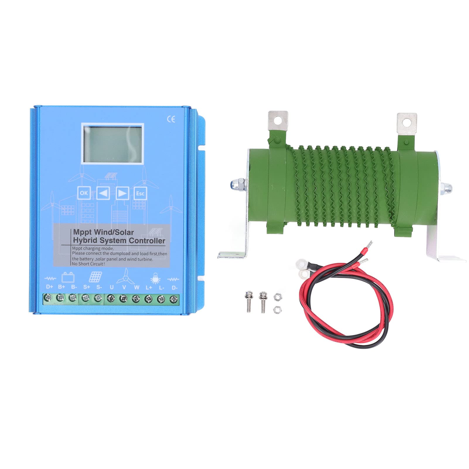
Figure 3.2: General perspective view of the Walfront Wind Solar Hybrid System Controller.
4. Specifications
| Parameter | Value |
|---|---|
| Model Number | Walfrontw9574is816 |
| System Voltage | 12V / 24V (Auto-identification) |
| Wind Turbine Charging Mode | Boost MPPT (Maximum Power Point Tracking) |
| Solar Panel Charging Mode | MOS tube series PWM (Pulse Width Modulation) |
| Maximum Wind Power | 800W (for 24V system), 600W (for 12V system) - Note: Max power depends on system voltage. |
| Maximum Solar Power | (Not explicitly stated, but typically matches wind power capacity or is specified separately. Assume combined capacity up to 800W/600W for hybrid systems if not specified.) |
| Display | Large LCD Screen |
| Protection Features | Solar reverse charging, overcharge, undervoltage, overload, battery reverse connection, open circuit. |
| DC Load Output Modes | 3 configurable modes |
| Package Dimensions | 14.57 x 9.96 x 4.33 inches |
| Item Weight | 4.88 pounds |
| Batteries Required | No (for controller operation, but requires external battery bank) |
Physical Dimensions:

Figure 4.1: Dimensional drawing of the Walfront Wind Solar Hybrid System Controller, showing measurements in millimeters and inches.
5. Setup and Installation
Proper installation is crucial for the safe and efficient operation of your hybrid system. Follow these steps carefully.
Installation Location:
- Mount the controller vertically on a non-flammable surface.
- Ensure adequate clearance around the controller for proper heat dissipation.
- Protect the controller from direct sunlight, rain, and excessive dust.
Wiring Sequence:
WARNING: Incorrect wiring order can damage the controller and other components. Always connect in the specified sequence.
- Connect the Dump Load: First, connect the external unloading resistor (dump load) to the designated terminals (U, V, W). This is critical for wind turbine safety.
- Connect the Battery: Connect the battery bank to the controller's battery terminals (B+, B-). Ensure correct polarity. The controller will automatically detect 12V or 24V.
- Connect the Solar Panels: Connect the solar panel array to the solar input terminals (S+, S-). Observe correct polarity.
- Connect the Wind Turbine: Connect the wind turbine to the wind input terminals (D+, D-).
- Connect DC Loads (Optional): If using DC loads, connect them to the load output terminals (L+, L-).
After all connections are made, the controller's LCD screen should power on and display system parameters.
6. Operating Instructions
The controller features a user-friendly LCD screen and four buttons for navigation and settings.
Button Functions:
- OK: Confirm selection or enter menu.
- Up Arrow (▲): Navigate up or increase value.
- Down Arrow (▼): Navigate down or decrease value.
- Esc: Exit menu or cancel operation.
LCD Display:
The LCD screen displays various real-time system parameters, including:
- Battery Voltage
- Battery Charge Level
- Wind Turbine Charging Current/Power
- Solar Panel Charging Current/Power
- Load Output Status and Mode
- System Temperature
- Error Codes (if any)
Parameter Settings:
The controller allows for both automatic and manual parameter settings.
- Automatic Settings: Upon initial power-up and battery connection, the controller will automatically identify the battery voltage (12V or 24V) and apply default charging parameters.
- Manual Adjustment: Users can enter the settings menu using the "OK" button to customize parameters such as:
- Battery Type (if applicable, though auto-identification is primary)
- Charge Voltage Limits
- Discharge Voltage Limits
- Load Control Modes (e.g., always on, dusk-to-dawn, timed)
Refer to the on-screen menu for specific parameter names and ranges.
7. Maintenance
Regular maintenance helps ensure the longevity and optimal performance of your controller.
- Visual Inspection: Periodically check the controller and all connections for any signs of damage, corrosion, or loose wiring.
- Cleaning: Keep the controller clean and free of dust. Use a dry, soft cloth. Do not use liquid cleaners.
- Ventilation: Ensure that the ventilation openings are not blocked to allow for proper airflow.
- Battery Check: Regularly inspect your battery bank according to the battery manufacturer's guidelines.
8. Troubleshooting
If you encounter issues with your controller, refer to the following common problems and solutions.
| Problem | Possible Cause | Solution |
|---|---|---|
| Controller LCD is off | No power from battery or reverse polarity. | Check battery connections and polarity. Ensure battery voltage is within operating range. |
| No charging from solar panels | Solar panels disconnected, shaded, or reverse polarity. | Check solar panel connections and polarity. Ensure panels are receiving adequate sunlight. |
| No charging from wind turbine | Wind turbine disconnected, insufficient wind, or dump load not connected. | Check wind turbine connections. Ensure sufficient wind speed. Verify dump load is correctly connected to U, V, W terminals. |
| "No Short Circuit!" message on display | This is an informational message indicating the system is operating normally without short circuits. | No action required. This is a status message, not an error. |
| Overcharge/Over-discharge warning | Battery voltage exceeded limits. | Check battery health. Verify charging parameters are set correctly for your battery type. |
For issues not covered here, please contact Walfront customer support.
9. Warranty and Support
Walfront products are manufactured to high-quality standards. For warranty information, please refer to the documentation provided with your purchase or contact your retailer.
For technical support or inquiries, please visit the Walfront brand store on Amazon or contact the seller directly through your Amazon order history.