
1. Introduction
This manual provides detailed instructions for the safe and effective use of the QIYQTIG BTS7960 IBT-2 43A Half-Bridge PWM Motor Driver Board. Please read this manual thoroughly before installation and operation to ensure proper functionality and to prevent damage to the module or connected devices.
2. Product Overview
The BTS7960 IBT-2 is a high-power H-bridge motor driver module designed for controlling DC motors. It is capable of handling significant current and features integrated protection mechanisms.
- High Power Capability: Controls high-power DC motors, delivering up to 43A.
- Wide Supply Voltage Range: Operates with supply voltages from 6V to 27V.
- Thermal Over-temperature Protection: Automatically protects the module from overheating.
- Undervoltage Shutdown: Shuts down if the supply voltage drops below 5.4V, restarting when voltage is 5.5V or higher.
- H-Bridge Configuration: Utilizes BTS7960 chips for robust motor control, allowing for forward and reverse operation.

Figure 2.1: Two QIYQTIG BTS7960 IBT-2 motor driver boards, showcasing their compact design with integrated heatsinks.
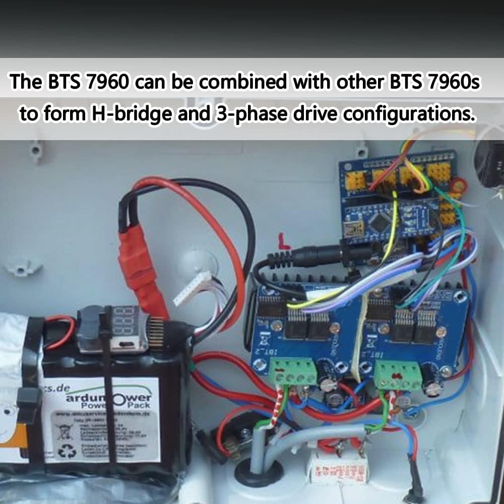
Figure 2.2: Example of BTS7960 modules combined to form an H-bridge configuration for motor control.
3. Specifications
| Parameter | Value |
|---|---|
| Maximum Current | 43A |
| Supply Voltage | 6V - 27V DC |
| Input Level | 3.3V - 5V |
| Material | Copper (Heatsink) |
| Item Weight | 0.13 Kilograms |
| Color | Blue (PCB) |

Figure 3.1: Physical dimensions of the BTS7960 IBT-2 module.
4. Setup and Wiring
Careful wiring is crucial for the correct and safe operation of the motor driver. Ensure all connections are secure before applying power.
4.1 Pinout Description

Figure 4.1: Detailed pinout of the BTS7960 IBT-2 module, showing power, motor, and control pins.
| Pin No. | Function | Description |
|---|---|---|
| B- | Negative Motor Power Supply Ground | Connect to the negative terminal of the motor power supply. |
| B+ | Positive Motor Power Supply (6-27VDC) | Connect to the positive terminal of the motor power supply. |
| M+ | Motor Output + | Connect to one terminal of the DC motor. |
| M- | Motor Output - | Connect to the other terminal of the DC motor. |
| VCC | Logic Power Supply (5V) | Connect to 5V from your microcontroller (e.g., Arduino). |
| GND | Logic Ground | Connect to ground of your microcontroller. |
| R_IS | Right Current Sense | Current feedback for the right half-bridge. |
| L_IS | Left Current Sense | Current feedback for the left half-bridge. |
| R_EN | Right Enable | Enable pin for the right half-bridge. High to enable. |
| L_EN | Left Enable | Enable pin for the left half-bridge. High to enable. |
| RPWM | Right PWM Input | PWM signal for controlling the right half-bridge (motor direction/speed). |
| LPWM | Left PWM Input | PWM signal for controlling the left half-bridge (motor direction/speed). |
4.2 Basic Wiring Diagram
The following diagram illustrates a typical wiring setup for controlling a DC motor with the BTS7960 IBT-2 module using a microcontroller (e.g., Arduino).

Figure 4.2: Basic wiring diagram showing connections for motor power, motor output, and logic control signals.

Figure 4.3: Example wiring diagram for connecting the BTS7960 IBT-2 to an Arduino board for control.
- Connect the motor power supply (6-27V DC) to the B+ (positive) and B- (negative) terminals on the driver board.
- Connect your DC motor to the M+ and M- output terminals.
- Connect the 5V logic power from your microcontroller to the VCC pin on the driver board.
- Connect the ground of your microcontroller to the GND pin on the driver board.
- Connect the RPWM and LPWM pins to PWM-capable digital output pins on your microcontroller. These pins control the motor's direction and speed.
- Connect the R_EN and L_EN pins to digital output pins on your microcontroller. These pins enable/disable the respective half-bridge. For basic operation, they can often be tied high (to 5V) if not dynamically controlled.
- The R_IS and L_IS pins provide current feedback and can be connected to analog input pins on your microcontroller if current monitoring is desired.
5. Operating Instructions
The BTS7960 IBT-2 module uses PWM signals to control the speed and direction of a DC motor. The two PWM inputs, RPWM and LPWM, control the two half-bridges.
- Motor Forward: Apply a PWM signal to RPWM and keep LPWM low (GND). The motor speed is proportional to the RPWM duty cycle.
- Motor Reverse: Apply a PWM signal to LPWM and keep RPWM low (GND). The motor speed is proportional to the LPWM duty cycle.
- Motor Stop (Brake): Keep both RPWM and LPWM low (GND).
- Motor Stop (Freewheel): Keep both RPWM and LPWM high (5V).
- Enable Pins (R_EN, L_EN): Ensure these pins are set high (5V) to enable the driver. Setting them low will disable the respective half-bridge.
It is critical to avoid applying high signals to both RPWM and LPWM simultaneously, as this can lead to a short circuit (shoot-through) and damage the driver.

Figure 5.1: The BTS7960 IBT-2 module connected to an Arduino, controlling a small DC fan, demonstrating a typical application.
6. Maintenance
The BTS7960 IBT-2 motor driver board is designed for durability and requires minimal maintenance. Follow these guidelines to ensure its longevity:
- Keep Clean: Ensure the module is free from dust, dirt, and moisture. Use a soft, dry brush or compressed air for cleaning.
- Environmental Conditions: Operate the module within its specified temperature and humidity ranges. Avoid extreme conditions.
- Inspect Connections: Periodically check all wiring connections for looseness or corrosion. Loose connections can lead to intermittent operation or damage.
- Avoid Physical Stress: Do not apply excessive force to the pins or the board itself.
7. Troubleshooting
If you encounter issues with your BTS7960 IBT-2 module, refer to the following troubleshooting steps:
| Problem | Possible Cause | Solution |
|---|---|---|
| Motor does not move. |
|
|
| Motor moves erratically or slowly. |
|
|
| Module gets excessively hot. |
|
|
| Module shuts down unexpectedly. |
|
|
8. Safety Information
Please observe the following safety precautions when working with the BTS7960 IBT-2 motor driver board:
- Power Off Before Wiring: Always disconnect all power supplies before making or changing any connections.
- Correct Voltage: Ensure the motor power supply voltage is within the specified 6V-27V range. Exceeding this can damage the module.
- Current Limits: Do not exceed the maximum current rating of 43A. Overcurrent can lead to overheating and permanent damage.
- Short Circuits: Prevent short circuits on the motor output terminals and power input terminals.
- ESD Protection: Handle the module with care to prevent electrostatic discharge (ESD) damage.
- Ventilation: Ensure adequate ventilation, especially when operating at high currents, to prevent overheating.
- Supervision: Do not leave the module unattended during initial testing or high-power operation.
9. Warranty and Support
Specific warranty information for this product is not provided in the available documentation. For support or warranty inquiries, please contact your retailer or the manufacturer, QIYQTIG, directly through their official channels.