1. Introduction
Welcome to the user manual for the GoolRC F4 V3S FC Flight Controller Board integrated with a 30A 4in1 Brushless ESC. This powerful and compact unit is designed for high-performance RC FPV drones and airplanes, offering advanced flight control capabilities and efficient motor management. This manual will guide you through the product's features, specifications, installation, configuration, and maintenance to ensure optimal performance and longevity.
2. Safety Precautions
Always observe the following safety guidelines when handling and operating electronic components for RC models:
- Power Source: Ensure the power source (battery) is disconnected before performing any wiring, soldering, or maintenance.
- Soldering Safety: Use appropriate ventilation when soldering. Wear eye protection. Be aware of hot components.
- Static Electricity: Handle the board by its edges to avoid static discharge, which can damage sensitive electronic components.
- Short Circuits: Double-check all connections for correct polarity and ensure no wires are short-circuited before applying power.
- Motor Safety: Motors can spin up unexpectedly. Always remove propellers before connecting power for testing or configuration.
- Environmental Conditions: Avoid exposing the board to moisture, extreme temperatures, or excessive dust.
3. Product Overview
The GoolRC F4 V3S FC and 30A 4in1 ESC combine a robust flight controller with a powerful electronic speed controller into a single, compact stack. This design simplifies wiring and reduces the overall footprint, making it ideal for various drone builds.
3.1 Key Features
- Integrated F4 V3S Flight Controller and 30A 4in1 BLHeli_S ESC.
- STM32 F405 MCU for high-performance processing.
- Dshot support for precise motor control.
- On-board OSD (On-Screen Display) configurable via Betaflight.
- BMI270 Gyro for stable flight performance.
- SBUS / PPM and Spektrum DSMX ports for receiver compatibility.
- Memory card blackbox for flight data logging.
- Integrated Barometer (BMP280) for altitude hold.
- Dual BEC outputs: 5V3A and 9V3A for peripherals.
- On-board video filters for clean FPV feed.
3.2 Components and Layout
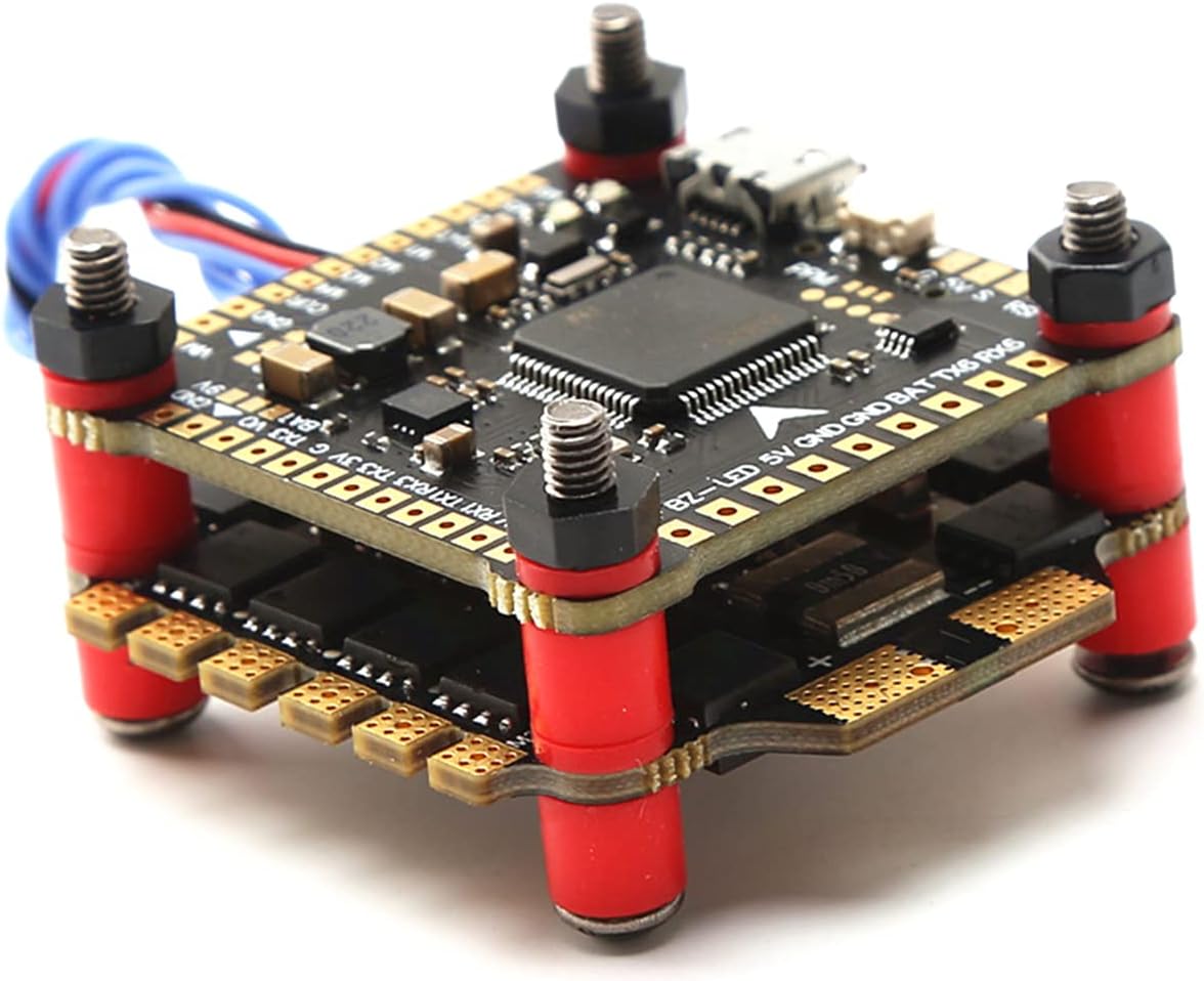
Figure 1: Overall view of the GoolRC F4 V3S FC and 30A 4in1 ESC stack. This image shows the two main boards (Flight Controller on top, ESC on bottom) connected by standoffs, with various ports and components visible.

Figure 2: Dimensions of the GoolRC F4 V3S FC and 30A 4in1 ESC. The board measures 36mm x 36mm, with standard 30.5mm x 30.5mm mounting holes.

Figure 3: Side view illustrating the various connection ports and pads on the flight controller board, including USB, receiver ports, and power pads.

Figure 4: Bottom view of the 4in1 ESC board, showing the motor pads and power input pads. This board handles power distribution and motor control.
4. Specifications
4.1 F4 V3S FC Flight Controller Board
| Feature | Specification |
|---|---|
| MCU | STM32 F405 |
| Gyro | BMI270 |
| Barometer | BMP280 |
| OSD | Betaflight OSD (Drag and Drop) |
| Blackbox | Memory card support |
| BEC Output | 5V3A, 9V3A |
| Video Filters | On-board (5V to VTX and camera) |
| Mounting Holes | 30.5mm x 30.5mm |
| Size | 36mm x 36mm |
4.2 4 in 1 30A BLHeli_S ESC
| Feature | Specification |
|---|---|
| Continuous Current | 30A |
| Peak Current (10s) | 35A |
| Input Voltage | 2-6S LiPo |
| BEC Output | 5V |
| Firmware | BLHeli_S |
| Programming | Yes |
| Weight | 9g |
| Size | 36mm x 36mm |
5. Setup
5.1 Wiring Diagram (General Guidance)
While a specific wiring diagram is not provided in the product details, the following general connections apply to most F4 FC and 4in1 ESC setups. Always refer to the latest Betaflight documentation and specific pinout diagrams for your board revision if available.
- Battery Input: Solder main battery leads (positive and negative) to the large BAT+ and GND pads on the ESC board.
- Motors: Solder motor wires to the corresponding M1, M2, M3, M4 pads on the ESC. Ensure correct motor order and rotation direction in Betaflight.
- Receiver: Connect your receiver's signal wire (e.g., SBUS, PPM, DSMX) to the designated RX pad on the FC. Provide 5V power and GND from the FC's BEC.
- VTX (Video Transmitter): Connect VTX video input to the VTX pad on the FC. Power the VTX from the 9V or 5V BEC output, depending on VTX requirements.
- Camera: Connect camera video output to the CAM pad on the FC. Power the camera from the 5V BEC output.
- Buzzer: Connect a buzzer to the BZ+ and BZ- pads.
- LEDs: Connect programmable LEDs to the LED pad.
5.2 Firmware Flashing
The flight controller typically comes pre-flashed with Betaflight firmware, and the ESCs with BLHeli_S. However, you may need to update or re-flash them for new features or troubleshooting.
- Betaflight FC Firmware:
- Download and install the latest Betaflight Configurator from GitHub.
- Connect the FC to your computer via a USB cable.
- In Betaflight Configurator, go to the 'Firmware Flasher' tab.
- Select the correct target (e.g., OMNIBUSF4SD or similar F4 target) and the latest stable firmware version.
- Click 'Load Firmware [Online]' and then 'Flash Firmware'.
- BLHeli_S ESC Firmware:
- Download and install BLHeliSuite32 or use the BLHeli Configurator Chrome app.
- Connect the FC to your computer via USB.
- In Betaflight Configurator, go to the 'Motors' tab and enable 'ESC/Motor Features' (if not already).
- Open BLHeliSuite32/Configurator, select 'BLHeli_S (4-way interface)' and connect.
- Read setup, flash the latest BLHeli_S firmware, and configure motor direction if needed.
5.3 Initial Configuration (Betaflight)
After flashing, proceed with basic configuration in Betaflight Configurator:
- Ports Tab: Configure UARTs for your receiver, VTX, GPS, etc.
- Configuration Tab: Select your ESC protocol (DSHOT600 recommended), accelerometer alignment, and other basic settings.
- Receiver Tab: Verify receiver input and channel mapping.
- Modes Tab: Set up arming, flight modes (Angle, Acro, Horizon), and other switches.
- Motors Tab: Test motor direction (without propellers!) and calibrate ESCs if necessary.
- OSD Tab: Customize your On-Screen Display elements.
6. Operating
6.1 Pre-Flight Checks
Before every flight, perform the following checks:
- Physical Inspection: Check for any loose wires, damaged components, or debris.
- Propellers: Ensure propellers are securely attached and in the correct orientation.
- Battery: Verify battery voltage is adequate and fully charged.
- Radio Link: Confirm your radio transmitter is powered on and linked to the receiver.
- Arming: Ensure the drone arms correctly and motors spin in the expected direction (without props, for ground testing).
6.2 First Flight Considerations
For your initial flights, choose an open area free from obstacles and people. Start with gentle maneuvers to get a feel for the drone's response. Gradually increase complexity as you gain confidence. Always be prepared to disarm the drone in an emergency.
7. Maintenance
Regular maintenance helps ensure the longevity and reliability of your flight controller and ESC:
- Cleaning: Periodically clean the boards with compressed air or a soft brush to remove dust and debris. Avoid using liquids.
- Inspection: Regularly inspect solder joints for cracks or cold joints. Check for any signs of overheating on components (discoloration).
- Wire Management: Ensure all wires are neatly routed and secured to prevent them from interfering with propellers or other moving parts.
- Storage: Store the drone and its components in a dry, cool environment away from direct sunlight and extreme temperatures.
8. Troubleshooting
This section addresses common issues you might encounter:
| Problem | Possible Cause | Solution |
|---|---|---|
| FC not powering on / No LED lights | Incorrect power connection, short circuit, faulty USB cable. | Check battery connection polarity. Inspect for solder bridges or shorts. Try a different USB cable. |
| Motors not spinning / Uneven motor spin | Incorrect motor wiring, ESC calibration issue, DSHOT protocol mismatch, motor direction. | Verify motor wiring to ESC. Recalibrate ESCs (if using OneShot/MultiShot). Ensure DSHOT is selected in Betaflight. Adjust motor direction in BLHeliSuite. |
| No FPV video feed | Incorrect VTX/Camera wiring, VTX not powered, OSD not configured. | Check video signal and power connections to VTX/Camera. Ensure VTX is powered by correct BEC voltage. Verify OSD settings in Betaflight. |
| Receiver not detected | Incorrect UART selected, wrong receiver protocol, faulty receiver. | Check 'Ports' tab in Betaflight for correct UART. Ensure receiver protocol (SBUS, PPM, etc.) is selected in 'Configuration' tab. Re-bind receiver. |
| Drone drifts or is unstable | Incorrect accelerometer calibration, vibrations, PID tuning. | Calibrate accelerometer on a level surface. Check for loose components causing vibrations. Adjust PID values if necessary (advanced). |
9. Warranty and Support
GoolRC is committed to providing quality products. If you encounter any problems or have questions regarding your F4 V3S FC Flight Controller Board and 30A 4in1 Brushless ESC, please contact the GoolRC store or customer support channel where you purchased the product. Provide your purchase details and a clear description of the issue for prompt assistance.
For further support and resources, you may visit the official GoolRC store on Amazon: GoolRC Amazon Store.


