1. Product Overview
The PowMr 60A MPPT Solar Charger Controller is designed for efficient and safe charging of various battery types in 12V, 24V, 36V, and 48V automatic detection systems. It features advanced MPPT technology for high tracking efficiency and a user-friendly backlight LCD display for system monitoring and parameter customization.
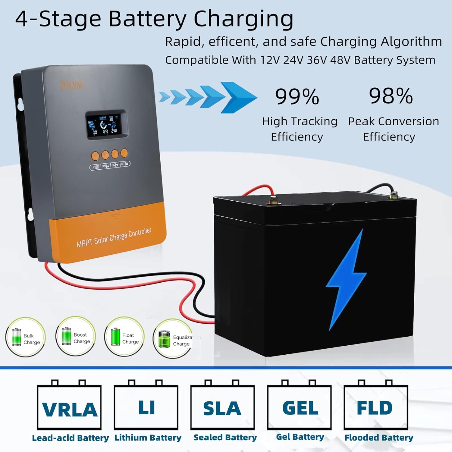
Figure 1: PowMr 60A MPPT Solar Charger Controller. This image shows the front of the controller with its LCD screen and four control buttons, along with icons representing solar panels, battery, and load.
2. Setup and Installation
2.1 Unboxing
Upon unboxing, verify that all components are present and undamaged. The package typically includes the MPPT solar charge controller, a user manual, and mounting accessories.
Video 1: PowMr 60A MPPT Solar Charge Controller Unboxing and Overview. This video demonstrates the unboxing process and highlights the physical features of the controller.
2.2 Mounting Recommendations
Install the controller in a well-ventilated area, away from direct sunlight, high temperatures, and water. Ensure sufficient room for air circulation around the heatsink. The controller can be mounted using the provided mounting holes.
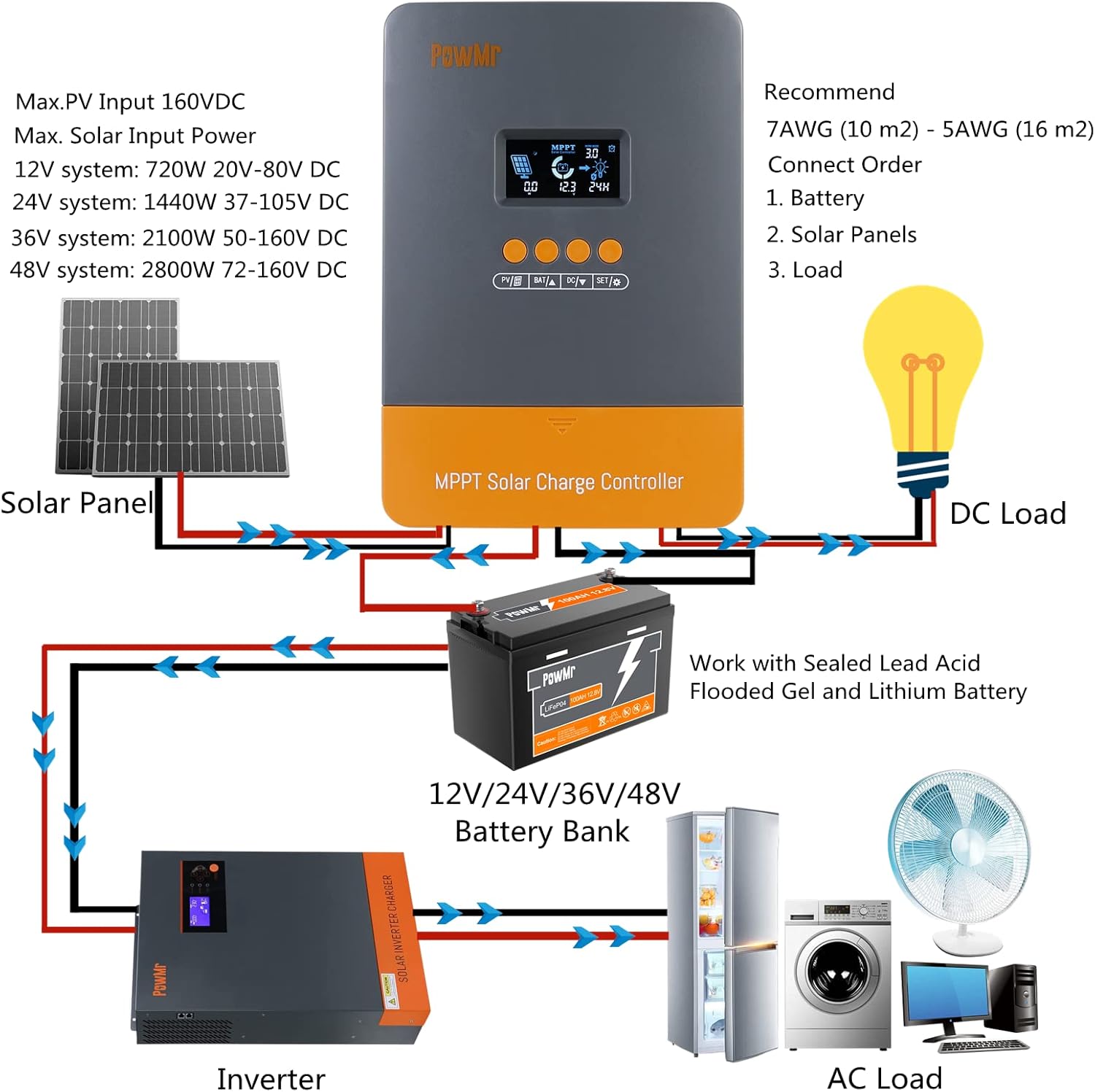
Figure 2: Wiring Diagram for PowMr 60A MPPT Solar Charger Controller. This diagram illustrates the correct connection order for the battery, solar panels, and DC load.
2.3 Wiring Steps
- Connect the Battery: First, connect the battery to the controller's battery terminals. Ensure correct polarity (positive to positive, negative to negative). Tighten all terminals securely to prevent loose connections.
- Connect the Solar Panels: Next, connect the solar panels to the controller's PV terminals. Observe correct polarity.
- Connect the Load (Optional): Finally, connect any DC loads to the load terminals.
Important: Always connect the battery first and disconnect it last to prevent damage to the controller.
Video 2: MPPT Solar Charge Controller Wiring and Operation Settings. This video demonstrates the physical wiring process for the controller, including battery and solar panel connections.
3. Operating Instructions
3.1 LCD Display and Buttons
The controller features a backlight LCD display that shows real-time system information. Four buttons (PV, BAT, DC, SET) allow for navigation and parameter adjustment.

Figure 3: Controller Interface Overview. This image labels the display screen, PV parameters, battery parameters, load parameters, save/restore function, and installation holes, along with the solar panel, battery, and load interfaces.
3.2 Parameter Setting
- Browse PV Parameters: Press the "PV" button to view specific parameters of the PV array, such as voltage, current, and power.
- Modify Battery Type/Charging Parameters: When the display shows "battery type" or a voltage value (e.g., C13.6V), press and hold the "BAT/up" button until the value flashes. Then, use the "up" or "down" buttons to adjust the value. Press "SET" to confirm and save.
- Load Mode Setting: Press and hold the "DC" button until "load value" flashes. Use the "up" or "down" buttons to modify the setting. Press "SET" to save. Available load modes include:
- 00H: Load Turn Off
- 24H: Load always Turn On
- 01H-23H: Time Control (Set load On's duration)
Video 3: How to operate the PowMr 60A MPPT Solar Charge Controller. This video provides a detailed guide on navigating the controller's interface and adjusting various settings.
4. Battery Charging Parameters
The controller supports multiple battery types including Sealed Lead-Acid, Flooded, Gel, and Lithium (LiFePO4). Customizable charging voltages are available for user-defined battery types.
| Battery Type | Boost Voltage | Float Voltage | Low Voltage Reconnect |
|---|---|---|---|
| Gel | 14.2V | 13.8V | 10V |
| Sealed | 14.4V | 13.8V | 10V |
| Flooded | 14.6V | 13.8V | 10V |
| Li (LiFePO4) | 14.4V | --- | 10V |
| User | 13.9-18V | 12.5-14.4V | 8-12.3V |
The controller features a 4-stage charging algorithm: Bulk Charge, Boost Charge, Float Charge, and Equalization, ensuring rapid, efficient, and safe battery charging.
5. Maintenance
The die-cast aluminum design of the controller ensures good heat dissipation, reducing noise and saving energy. Regularly check for clear ventilation around the heatsink to maintain optimal performance. Keep the unit free from dust and moisture.

Figure 4: Efficient Heat Sink Design. This image highlights the die-cast aluminum heat sink of the controller, emphasizing its role in heat dissipation.
6. Troubleshooting
The controller's self-diagnostic capability can assess and protect against various issues. Error codes are displayed on the LCD screen to help identify problems.
| Code | Description | How To Solve |
|---|---|---|
| 18 | Input PV voltage is low | Increase the PV voltage |
| 60 | Over-temperature protection | Fan will work and temperature reduction automatically |
| 63 | Battery voltage is high | Battery high voltage protection and wait for recovery |
| 65 | Battery voltage is low | Battery over-discharge and wait for recovery |
| 71 | Input PV voltage is high | Decrease the PV voltage |
| 73 | Over-charging current | Decrease the PV power |
The controller also includes full system protection against PV array short circuit, PV overcurrent, load overload, load short circuit, PV reverse polarity, battery reverse polarity, and over-temperature.
7. Specifications
- Model: POW-M60-PRO
- Dimensions: 230 x 165 x 72mm (9.1 x 6.5 x 2.8 inches)
- Mounting Holes: 4 x Ø10mm
- Max Terminal Size: 16mm² / 5AWG
- Net Weight: 1.33 kg (2.9 lbs)
- Working Temperature: -35°C to +45°C
- Humidity Range: ≤ 95% (NC)
- Enclosure: IP32
- Altitude: < 3000m
- Voltage: 48 Volts (DC)
- Display Type: LCD
8. Warranty and Support
For after-sale service and support, please visit the official PowMr website at www.PowMr.com or contact support via email at Support@PowMr.com.


