
QIYQTIG JY01
JY01 DC Brushless Motor Controller User Manual
Model: JY01
Brand: QIYQTIG
1. Introduction
This user manual provides detailed instructions for the installation, operation, and maintenance of the QIYQTIG JY01 DC Brushless Motor Controller. This controller is designed for efficient and balanced control of DC brushless motors, suitable for various automotive and industrial applications.
Please read this manual thoroughly before using the product to ensure safe and optimal performance.
2. Safety Information
Always observe the following safety precautions to prevent injury or damage to the device:
- Ensure the power supply voltage is within the specified range (DC 12V-36V).
- Do not exceed the maximum driver power of 500W.
- Disconnect power before making any connections or disconnections.
- Avoid short circuits between terminals.
- Operate the controller within the specified temperature range (-40°C to 85°C).
- Keep the device away from moisture, dust, and corrosive environments.
- Only qualified personnel should perform installation and maintenance.
3. Product Overview
3.1 Features
- Wide operating voltage range: DC 12V-36V.
- High peak current capability: 20A.
- Supports up to 500W motor power.
- Adjustable speed control via 0.1V-5V voltage input.
- Compact and robust design for various applications.
3.2 Components
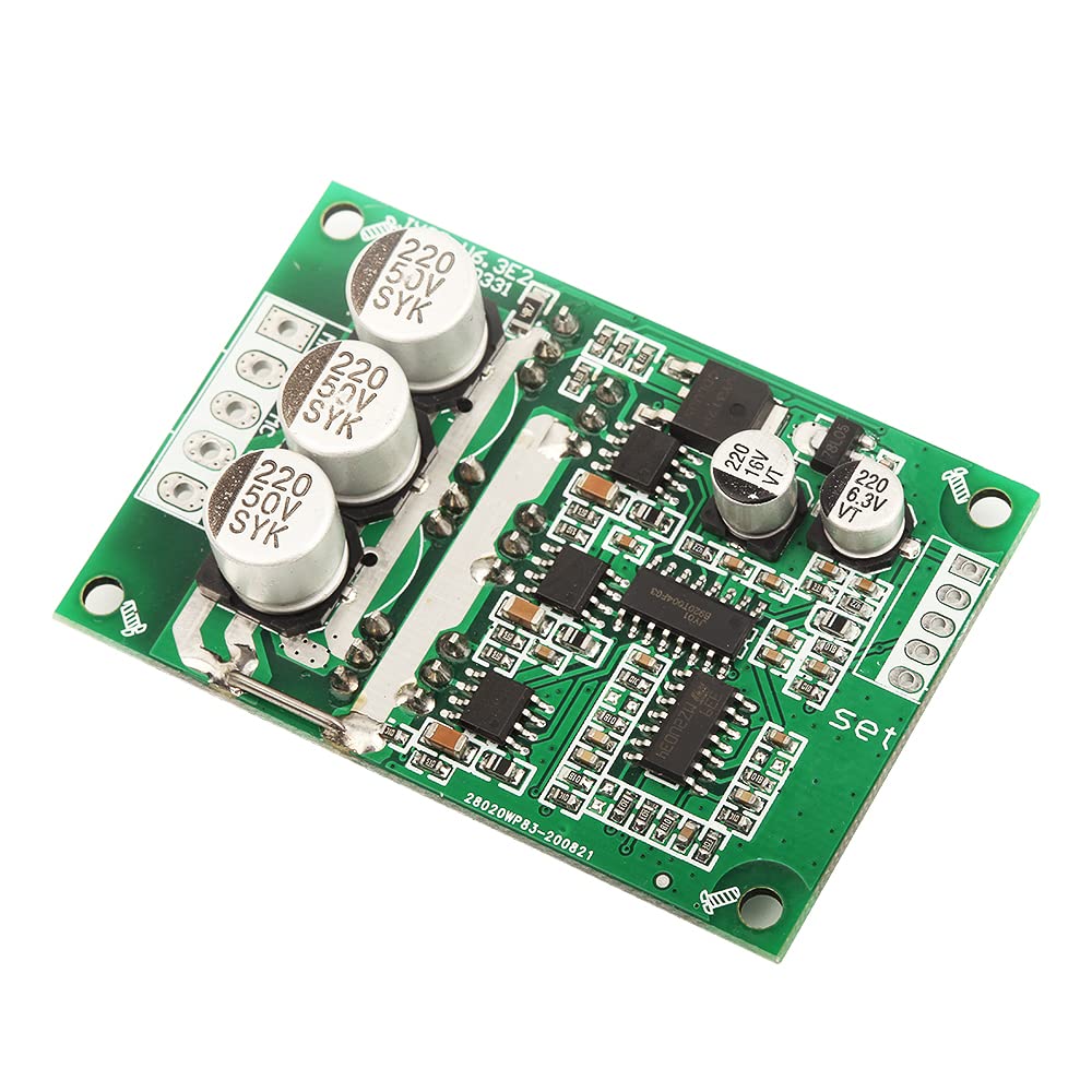
The JY01 controller board features various components for power management, motor control, and signal processing. Refer to the images below for visual identification of key parts.



4. Specifications
| Parameter | Value |
|---|---|
| Operating Voltage | DC 12V-36V |
| Peak Current | 20A |
| Driver Power | <500W |
| Speed Voltage Input | 0.1V-5V |
| Operating Temperature | -40°C to 85°C |
| Dimensions | (Not provided in source data, typical for such boards) |
| Weight | (Not provided in source data) |
5. Setup and Wiring
Proper wiring is crucial for the correct operation of the JY01 controller. Follow these steps carefully:
- Power Connection: Connect your DC power supply (12V-36V) to the VCC (positive) and GND (negative) terminals on the controller board. Ensure correct polarity.
- Motor Connection: Connect the three phase wires of your brushless DC motor to the MA, MB, and MC terminals on the controller. The order may affect rotation direction; if needed, swap any two phase wires to reverse direction.
- Hall Sensor Connection (if applicable): If your motor has Hall sensors, connect them to the corresponding Hall sensor input terminals (5V, GND, Ha, Hb, Hc). If your motor is sensorless, these connections are not required.
- Speed Control Input: Connect your speed control signal (0.1V-5V) to the "Speed" or "SET" input terminal. This can be from a potentiometer, PLC, or other voltage source.
- Direction Control (if applicable): Some controllers may have a direction control input (e.g., Z-F). Refer to the board markings for specific functionality.
Note: Always double-check all connections before applying power to prevent damage to the controller or motor.
6. Operating Instructions
Once the controller is correctly wired, follow these steps to operate your brushless DC motor:
- Power On: Apply the specified DC voltage (12V-36V) to the controller. The controller should power up.
- Speed Adjustment: Adjust the voltage on the speed control input (0.1V-5V) to control the motor's rotational speed. A higher voltage typically results in higher speed.
- Monitoring: Observe the motor's operation. Listen for unusual noises or vibrations, which may indicate an issue.
- Power Off: To stop the motor, reduce the speed control voltage to its minimum or disconnect the main power supply.
For optimal performance, ensure the motor is not overloaded and that adequate cooling is provided for both the motor and the controller, especially during prolonged operation at high power.
7. Maintenance
The JY01 DC Brushless Motor Controller is designed for low maintenance. However, periodic checks can extend its lifespan and ensure reliable operation:
- Cleaning: Keep the controller board clean and free from dust, dirt, and debris. Use a soft, dry brush or compressed air for cleaning. Do not use liquids.
- Connection Checks: Periodically inspect all wiring connections to ensure they are secure and free from corrosion. Loose connections can lead to intermittent operation or damage.
- Environmental Conditions: Ensure the operating environment remains within the specified temperature and humidity ranges. Avoid exposure to extreme conditions.
- Heat Management: Verify that the controller has adequate ventilation, especially if operating near its maximum power rating. Ensure no obstructions block airflow to the heat dissipation areas.
8. Troubleshooting
If you encounter issues with your JY01 controller, refer to the following table for common problems and their solutions:
| Problem | Possible Cause | Solution |
|---|---|---|
| Motor does not start | No power supply; Incorrect wiring; Faulty motor; Speed input too low. | Check power connections and voltage; Verify motor and Hall sensor wiring; Test motor independently; Increase speed control voltage. |
| Motor runs erratically or vibrates | Incorrect motor phase wiring; Faulty Hall sensors (if used); Overload. | Swap two motor phase wires; Check Hall sensor connections/functionality; Reduce load on the motor. |
| Controller overheats | Excessive load; Insufficient ventilation; Short circuit. | Reduce motor load; Ensure proper airflow around the controller; Check for any short circuits in wiring. |
| Motor runs in wrong direction | Incorrect motor phase wiring. | Swap any two of the three motor phase wires (MA, MB, MC). |
If the problem persists after attempting these solutions, contact customer support for further assistance.
9. Warranty and Support
QIYQTIG products are manufactured to high quality standards. For specific warranty terms and conditions, please refer to the product packaging or the official QIYQTIG website. Keep your purchase receipt as proof of purchase.
For technical support, troubleshooting assistance, or inquiries about replacement parts, please contact QIYQTIG customer service through the contact information provided with your purchase or on the brand's official channels.
Related documentsJY01

Ask a question about this manual
Ask about setup, troubleshooting, compatibility, parts, safety, or missing instructions. Manuals+ will review the question and use this page’s manual context to help answer it.