1. Product Overview
The DieseRC Wireless Remote Control Switch is a versatile 433Mhz RF relay receiver designed for controlling various electrical devices. It offers stable and reliable performance with high reception sensitivity, allowing control within approximately 30 meters in open areas, even through walls and doors. This product is ideal for home automation, industrial control, and DIY projects.

The system includes a relay receiver and a transmitter keyfob. The receiver features potential-free contacts (dry contacts) and operates on a wide voltage range of 100V to 250V AC. The high-quality 5A relay ensures durability with over 100,000 operations. One receiver can store up to 20 transmitters, and a single transmitter can control multiple receivers simultaneously. The secure EV1527 learning code technology enhances security.
2. Product Details and Components
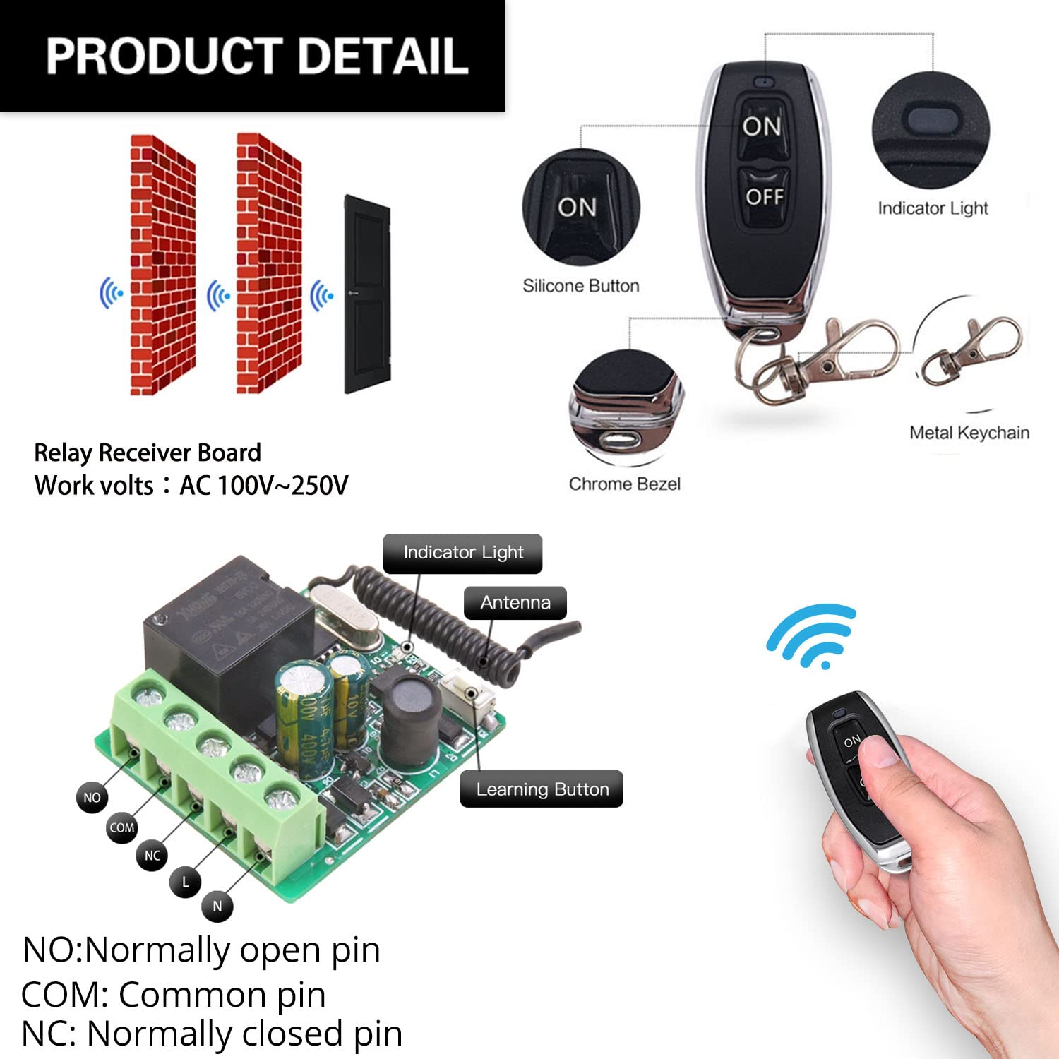
Familiarize yourself with the main components of the DieseRC relay receiver and remote control.

- NO (Normally Open Pin): Contact is open when the relay is de-energized.
- COM (Common Pin): The common terminal for the relay contact.
- NC (Normally Closed Pin): Contact is closed when the relay is de-energized.
- L & N: Live and Neutral input terminals for power supply (AC 100V~250V).
- Indicator Light: Provides visual feedback on the receiver's status.
- Antenna: For receiving RF signals from the transmitter.
- Learning Button: Used for programming and resetting the receiver.
3. Setup and Wiring
Before connecting, ensure the power supply is disconnected. The receiver supports AC 100V~250V input. The relay provides potential-free (dry) contacts, meaning it acts as a switch without providing power to the connected device. You will need to supply power to your device separately.
3.1 Wiring Diagrams
- AC Device Control: Connect the AC power source to the L and N terminals of the receiver. Connect your AC device (e.g., lamp) to the NO and COM terminals.
- DC Device Control: Connect the AC power source to the L and N terminals of the receiver. Connect your DC device to the NO and COM terminals, ensuring the DC power supply is also connected to the device.
- Passive Output (Dry Contact): For applications requiring a simple switch closure, connect the device's control circuit to the NO and COM terminals. The receiver itself does not supply power through these contacts.

For garage door openers, the relay acts as a momentary switch. Connect the NO and COM terminals to the wall button/console terminals of your existing wired garage door opener. The receiver's L and N terminals should be connected to an AC 100-250V power source.
3.2 Initial Pairing and Reset
Before programming new modes, it is recommended to reset the receiver to clear any previous pairings.
- Reset: Press the learning button on the receiver 8 times. The indicator light will flash rapidly, then turn off, indicating successful reset. All previously paired remote controls will no longer work.
4. Operating Modes and Programming
The DieseRC receiver supports four operating modes: Momentary, Toggle, Latched, and Delay. You can program the receiver to your desired mode by following the steps below.


4.1 Momentary Mode (Press and Hold)
In Momentary mode, the relay activates only while the remote button is pressed and held. It deactivates upon release.
- Press the learning button on the receiver 1 time. The indicator light will turn on.
- Press any button on your remote control. The indicator light will flash, then turn off, indicating successful pairing.
4.2 Toggle Mode (Press On/Off)
In Toggle mode, pressing the remote button once activates the relay, and pressing it again deactivates it.
- Press the learning button on the receiver 2 times. The indicator light will turn on.
- Press any button on your remote control. The indicator light will flash, then turn off, indicating successful pairing.
4.3 Latched Mode (Separate On/Off Buttons)
In Latched mode, one button on the remote activates the relay, and another button deactivates it. This mode requires a remote with at least two distinct buttons (e.g., ON and OFF).
- Press the learning button on the receiver 3 times. The indicator light will turn on.
- Press the 'ON' button on your remote control. The indicator light will flash.
- Press the 'OFF' button on your remote control. The indicator light will flash, then turn off, indicating successful pairing.
4.4 Delay Mode (Timed Off)
In Delay mode, the relay activates when the remote button is pressed and held, and automatically deactivates after a set time (5, 10, 15, or 20 seconds) upon release.
- Press the learning button on the receiver 4, 5, 6, or 7 times to set the delay time:
- 4 times for 5-second delay
- 5 times for 10-second delay
- 6 times for 15-second delay
- 7 times for 20-second delay
- Press any button on your remote control. The indicator light will flash, then turn off, indicating successful pairing.
5. Applications
The DieseRC Wireless Remote Control Switch is highly versatile and can be used in a wide range of applications:

- Home Automation: Control lights, fans, and other appliances remotely.
- Garage Door Openers: Integrate with existing wired garage door systems for remote access.
- Electric Locks & Door Systems: Provide remote control for access systems.
- Ventilation Devices: Remotely switch on/off exhaust fans or other ventilation units.
- Water Pumps: Control small water pumps for irrigation or other purposes.
- Signal Transmission: Use for various signal transmission applications.
- DIY Projects: A flexible component for custom remote control solutions.
6. Maintenance
To ensure the longevity and optimal performance of your DieseRC Wireless Remote Control Switch, follow these maintenance guidelines:
- Battery Replacement (Transmitter): The transmitter keyfob uses 2 CR2016 batteries. To replace them, locate the screw port on the back of the transmitter, disassemble the casing, and replace the batteries. Ensure correct polarity.
- Cleaning: Use a soft, dry cloth to clean the receiver and transmitter. Do not use harsh chemicals or abrasive cleaners.
- Environment: Avoid exposing the devices to extreme temperatures, high humidity, or direct sunlight. Keep them away from strong electromagnetic fields.
- Inspection: Periodically check wiring connections to ensure they are secure and free from damage.
7. Troubleshooting
If you encounter issues with your DieseRC Wireless Remote Control Switch, try the following troubleshooting steps:
- Remote Not Responding:
- Check if the transmitter battery is depleted. Replace if necessary.
- Ensure the receiver is powered on and its indicator light is active.
- Verify that the remote is properly paired to the receiver in the correct operating mode (refer to Section 4). If unsure, perform a reset (Section 3.2) and re-program the desired mode.
- Limited Range:
- Ensure there are no significant obstructions (thick walls, metal structures) between the transmitter and receiver.
- Avoid placing the receiver near large metal objects or other devices that emit strong RF signals, which can cause interference.
- Check the receiver's antenna for any damage or obstruction.
- Device Not Activating/Deactivating:
- Confirm that the wiring connections to your device are correct and secure (refer to Section 3.1).
- Ensure the connected device is functioning correctly when directly powered or switched.
- Verify that the operating mode programmed is suitable for your application (e.g., Momentary for garage doors, Toggle for lights).
- Indicator Light Not Functioning:
- Check the power supply to the receiver.
- If the receiver is powered but the light is off and it's not responding, the unit may be faulty.
8. Specifications
| Feature | Specification |
|---|---|
| Model Number | RX26 |
| Operating Voltage | AC 100V~250V |
| Operating Frequency | 433Mhz |
| Relay Type | Potential-Free Contacts (Dry Contacts) |
| Relay Current Rating | 5A |
| Remote Control Battery | 2 x CR2016 (included) |
| Learning Code | EV1527 |
| Control Distance | Up to 30 meters (open area) |
| Country of Origin | China |
9. Warranty and Support
For any inquiries, technical support, or warranty claims, please contact the manufacturer/importer directly.

Manufacturer/Importer: Huizhou Wenqiao Electronic Technology Co., Ltd.
Address: Room 03, 12th Floor, Building T19, East Coast Garden, Fangzhilonghuwan, No. 27, Sanhuan South Road, Huicheng District, Huizhou City, Guangdong Province, China 516001
Service Email: dieseelectronic@163.com
Please retain your purchase receipt for warranty purposes.