
1. Introduction
The Micsig SATO1004 is a 100MHz digital handheld portable automotive oscilloscope designed for precise signal testing and measurement in automotive applications. It features a 1GSa/s sample rate, 70Mpts memory depth, and a 4-channel input, making it suitable for various diagnostic tasks.
This manual provides essential information for setting up, operating, and maintaining your SATO1004 oscilloscope. Please read it thoroughly before use to ensure proper functionality and safety.
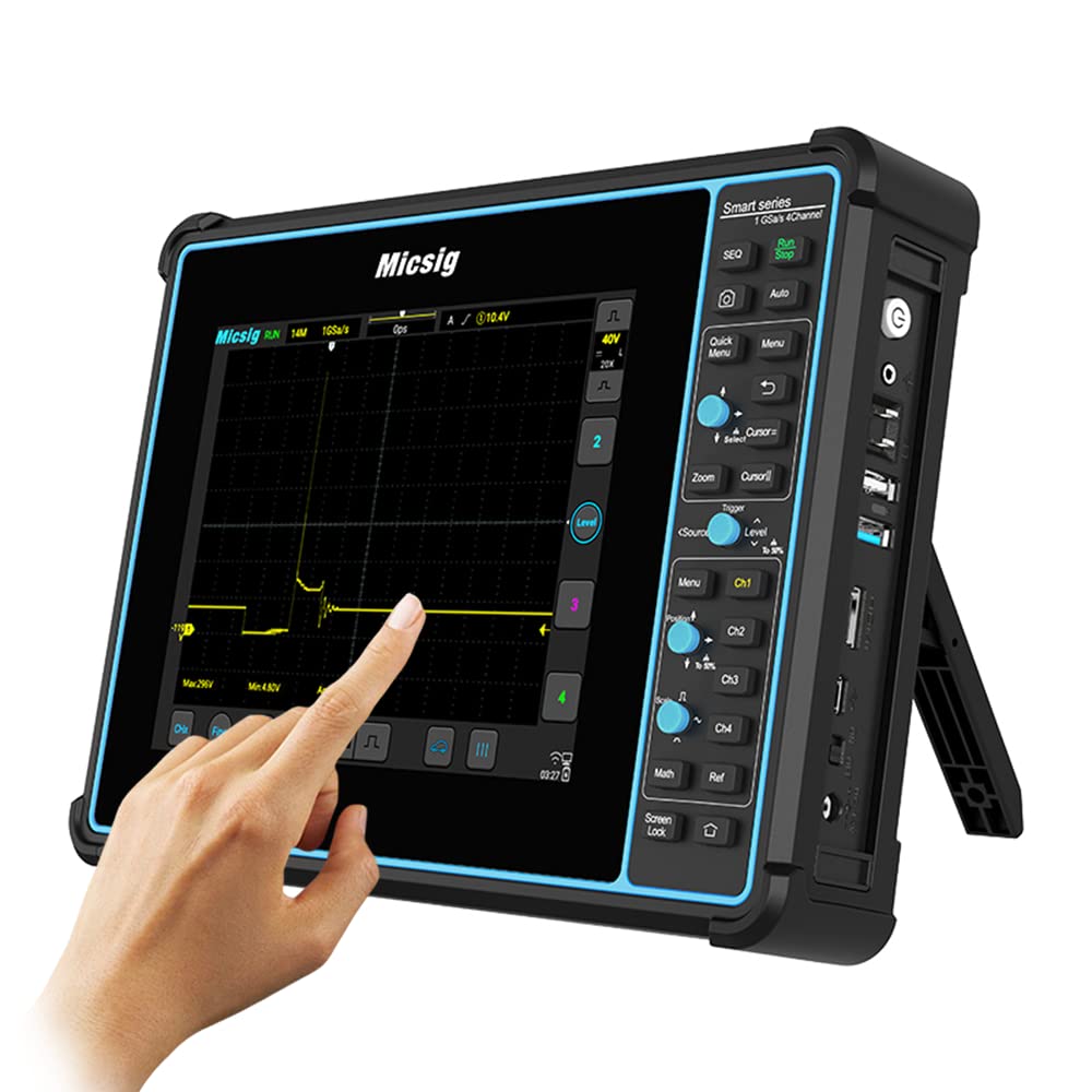
Image: Front view of the Micsig SATO1004 Automotive Oscilloscope, displaying a waveform and automotive graphic.
2. Package Contents
Verify that all items listed below are included in your package. If any items are missing or damaged, please contact Micsig support.
- Micsig SATO1004 Automotive Oscilloscope (with built-in battery)
- Power Cord
- 2 pairs of Alligator Clips
- 2 pairs of Soft Pin Probes
- 2 Passive Probes
- 4 x BNC to Banana Leads
- 1 Adapter
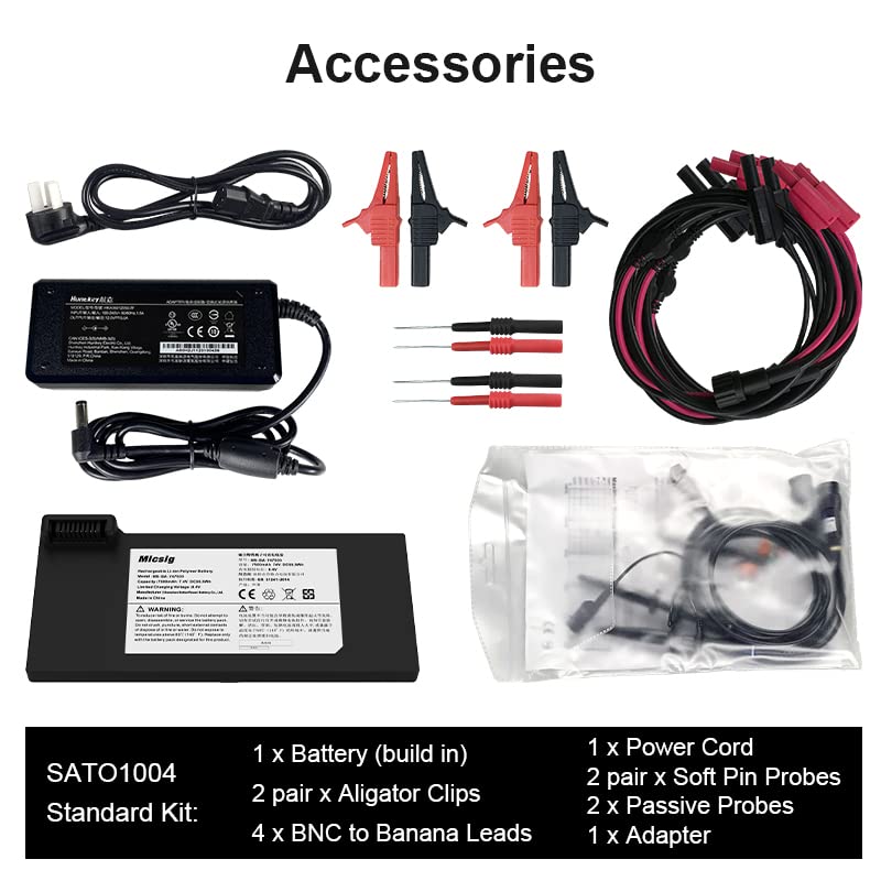
Image: A visual representation of the standard accessories included with the SATO1004, such as power cord, adapter, probes, alligator clips, and BNC to banana leads.
3. Setup
3.1 Initial Power On
- Ensure the oscilloscope is fully charged or connected to the power adapter using the provided power cord.
- Press and hold the power button located on the side of the device until the screen illuminates.
- The device will boot up, displaying the Micsig logo and then the main oscilloscope interface.
3.2 Connecting Probes and Leads
The SATO1004 features four analog channels. Connect the appropriate probes or leads to the BNC input connectors on the device. Ensure connections are secure.

Image: A probe connected to a component within an automotive engine, demonstrating a typical setup connection.
Video: An unboxing and initial setup guide for the Micsig SATO1004 oscilloscope, demonstrating how to connect accessories and power on the device.
4. Operating Instructions
The SATO1004 features a capacitive touch screen for intuitive operation. Most functions can be accessed directly via the touch interface or the physical buttons on the right side.
4.1 Basic Operation Steps
- Connect Wires: Attach the appropriate probes or leads to the test points on the vehicle or component.
- Select Test: On the oscilloscope screen, navigate to the desired automotive test function or measurement mode. The device offers various presets for common automotive diagnostics.
- Fine Adjust: Use the touch screen or physical controls to adjust parameters such as vertical scale (Volts/Div), horizontal scale (Time/Div), trigger level, and position to optimize the waveform display.

Image: A hand interacting with the touch screen of the Micsig SATO1004, demonstrating the ease of selecting tests and adjusting settings.
4.2 Key Features and Functions
- 100MHz Bandwidth: Capable of testing FlexRay, CAN FD, and LIN buses.
- 1GSa/s Sampling Rate: Ensures clear and accurate signal display.
- 70Mpts Memory Depth: Allows for detailed zoom-in on entire waveforms.
- Waveform Capture Rate: Up to 130,000 wfms/s for capturing transient events.
- Built-in Battery: 7500mAh Li-ion battery supports up to 5 hours of field work.
- Connectivity: Wi-Fi, USB 3.0/2.0 Host, USB Type-C, Grounding, HDMI output.

Image: The SATO1004 oscilloscope screen showing a detailed CAN bus waveform, highlighting its high bandwidth capability.
4.3 Automotive Test Applications
The SATO1004 is equipped with presets and capabilities for a wide range of automotive diagnostic tests:
- Engine Ignition Tests: Conduct tests on COP independent ignition, single/multi-cylinder ignition, with/without distributor, and pulse ignition systems.
- Sensor Tests: Test various sensors including ABS, accelerator, throttle position, intake pressure, air flow meter, crankshaft, camshaft, knock, and oxygen sensors.
- Network Tests: Supports CAN, LIN, FlexRay, and K-line network analysis.

Image: The oscilloscope screen displaying waveforms from engine ignition tests, illustrating the device's diagnostic capabilities.

Image: A series of waveforms representing various sensor tests, demonstrating the oscilloscope's versatility in automotive diagnostics.
Video: A demonstration of the Micsig SATO1004 and SATO2002 automotive digital oscilloscopes, showcasing their features and operational interface.
5. Maintenance
5.1 Cleaning
- Wipe the device exterior with a soft, damp cloth. Avoid abrasive cleaners or solvents.
- Ensure no liquid enters the ports or ventilation openings.
- Clean the screen with a microfiber cloth suitable for electronic displays.
5.2 Battery Care
- For optimal battery life, avoid fully discharging the battery frequently.
- Store the device in a cool, dry place when not in use for extended periods.
- Recharge the battery periodically if stored for a long time to prevent deep discharge.
5.3 Storage
When not in use, store the oscilloscope in its original packaging or a protective case to prevent damage from dust, moisture, and impacts. Ensure the power-off lock is engaged for safe transport and storage.
6. Troubleshooting
6.1 Common Issues and Solutions
| Problem | Possible Cause | Solution |
|---|---|---|
| Device does not power on. | Low battery or power adapter issue. | Connect to power adapter and charge. Ensure power adapter is working. |
| No waveform displayed. | Incorrect probe connection, wrong settings, or no input signal. | Check probe connections. Adjust vertical/horizontal scales and trigger settings. Verify signal source. |
| Screen is unresponsive. | Software glitch or temporary freeze. | Perform a soft reset by holding the power button for 10 seconds. If issue persists, contact support. |
| Inaccurate measurements. | Uncalibrated probes or incorrect probe attenuation settings. | Ensure probes are properly calibrated and attenuation settings on the oscilloscope match the probe. |
For issues not covered here, please refer to the Micsig official website or contact customer support.
7. Specifications
| Parameter | Value |
|---|---|
| Model | SATO1004 |
| Bandwidth | 100MHz |
| Analog Channels | 4 |
| Sampling Rate (Max.) | 1GSa/s (single channel) |
| Memory Depth | 70Mpts (single channel) |
| Display | 8" TFT-LCD (800*600), 14*10 grids |
| Battery | 7.4V, 7500mAh, Li-ion battery |
| Interfaces | Wi-Fi, USB 3.0/2.0 Host, USB Type-C, Grounding, HDMI out |
| Dimension/Net Weight | 265*192*50mm / 1.9kg (with battery) |
8. Warranty and Support
8.1 Return Policy
This product is eligible for a refund or replacement within 30 days of purchase, in accordance with the seller's return policy.
8.2 Customer Support
For technical assistance, warranty claims, or further inquiries, please contact MICSIG Direct, the seller of this product. Micsig is committed to providing professional and quick response after-sales support.
You can often find support contact information on the seller's page or through the platform where the product was purchased.


