
1. Introduction
This document provides comprehensive instructions for the MiOYOOW RS422 to TTL Converter Module. This module is designed for mutual conversion between 3.3V TTL and RS422 signals. It integrates overvoltage and overcurrent protection circuits to safeguard the RS422 level signal in real-time, ensuring the stable and reliable operation of the embedded SP3490 chip.
2. Product Features
- High Performance: The module supports overvoltage and overcurrent protection, enhancing reliability and safety.
- Enhanced Signal Transmission: Utilizing SMD components and robust connector pins, this module ensures improved signal integrity and electromagnetic compatibility (EMC), making it suitable for diverse and demanding environments.
- Ease of Use: Featuring a compact and lightweight design, the module is easy to install. It includes 2.54 pitch welding holes, providing convenient options for soldering and saving installation time.
- Practical Design: Equipped with power supply and transceiver indicator lights, the module allows users to visually monitor its operational status, including data sending and receiving.
3. Specifications
- Product Name:
- TTL Mutual Conversion RS422 Module
- Input Voltage:
- DC 3.3V
- Chip:
- SP3490
- Operating Temperature:
- -25℃ to 85℃ (-13°F to 185°F)
- Operating Humidity:
- 5% to 95%RH
- Dimensions (L x W x H):
- 50.7mm x 26.9mm x 10mm
- Compatible Devices:
- Desktop systems
- Connector Type:
- Serial Adapter
- Color:
- Red
- Number of Ports:
- 5
- Item Weight:
- 0.06 kg
- Package Quantity:
- 1
3.1 Product Dimensions
The module's physical dimensions are provided for integration planning.
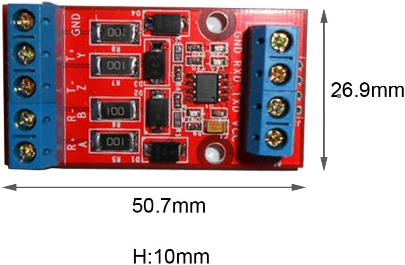
Figure 3.1: Module Dimensions
4. Setup and Interface Definition
Proper connection of the module is essential for correct operation. Refer to the diagram and definitions below for wiring.

Figure 4.1: Module Interface Pinout
4.1 Module 4-Pin Terminal Side (TTL/UART Interface)
- VCC: Connect to a 3.3V DC power supply.
- TXD: This is the TTL (UART) transmission pin of the module. Connect it to the RXD (receiving) pin of your microcontroller or host system.
- RXD: This is the TTL (UART) receiving pin of the module. Connect it to the TXD (transmitting) pin of your microcontroller or host system.
- GND: This is the ground wire for the module. It must be connected to the ground of your microcontroller system.
4.2 Module 5-Pin Terminal Side (RS422 Interface)
- R+/A: This pin of the module should be connected to the T+/Y pin of another RS422 module for receiving data.
- R-/B: This pin of the module should be connected to the T-/Z pin of another RS422 module for receiving data.
- T-/Z: This pin of the module should be connected to the R-/B pin of another RS422 module for transmitting data.
- T+/Y: This pin of the module should be connected to the R+/A pin of another RS422 module for transmitting data.
- GND: This is the ground wire for the RS422 interface. If conditions permit, this ground wire can be used as the return path for the common mode signal. It can be omitted if not required by the specific application.
5. Operating Instructions
Once the module is correctly wired according to the interface definitions:
- Power On: Apply 3.3V DC power to the VCC and GND pins of the TTL interface. The power indicator light on the module should illuminate, indicating it is powered.
- Data Transmission (TTL to RS422): When your microcontroller sends data via its TXD pin (connected to the module's RXD), the module will convert this TTL signal to RS422 and transmit it through its T+/Y and T-/Z pins. The TXD indicator light on the module will flash during transmission.
- Data Reception (RS422 to TTL): When an external RS422 device sends data to the module's R+/A and R-/B pins, the module will convert this RS422 signal to TTL and output it via its RXD pin (connected to the microcontroller's TXD). The RXD indicator light on the module will flash during reception.
- Monitoring: Observe the power, TXD, and RXD indicator lights to confirm the module's operational status and data flow.
6. Maintenance
To ensure the longevity and optimal performance of your MiOYOOW RS422 to TTL Converter Module:
- Cleanliness: Keep the module free from dust, dirt, and debris. Use a soft, dry cloth for cleaning.
- Environment: Avoid exposing the module to excessive moisture, extreme temperatures, or corrosive chemicals. Operate within the specified temperature and humidity ranges.
- Connections: Periodically check all wiring connections to ensure they are secure and free from damage.
- Storage: When not in use, store the module in a dry, cool place, away from direct sunlight.
7. Troubleshooting
If you encounter issues with your module, consider the following troubleshooting steps:
- No Power: Ensure the 3.3V DC power supply is correctly connected to the VCC and GND pins and is providing the correct voltage. Check if the power indicator light is on.
- No Data Transmission/Reception:
- Verify all TXD, RXD, R+/A, R-/B, T+/Y, T-/Z, and GND connections are correct and secure.
- Confirm that the microcontroller or external RS422 device is functioning correctly and sending/receiving data as expected.
- Check the TXD and RXD indicator lights on the module for activity during data transfer attempts.
- Intermittent Communication: This could be due to loose connections, electrical noise, or operating outside the specified environmental conditions. Recheck connections and ensure a stable operating environment.
- Overvoltage/Overcurrent Protection Triggered: If the module stops functioning unexpectedly, it might be due to the protection circuits. Disconnect power, inspect for any short circuits or incorrect voltage application, and then reconnect.
If problems persist after following these steps, please contact customer support.
8. Warranty Information
This MiOYOOW RS422 to TTL Converter Module is covered by a Limited Warranty. For specific terms, conditions, and duration of the warranty, please refer to the warranty documentation provided with your purchase or contact MiOYOOW customer support.
9. Customer Support
For any questions, technical assistance, or issues not resolved by the troubleshooting guide, please do not hesitate to contact MiOYOOW customer support. We are committed to providing satisfying solutions within 24 hours.
You can typically find contact information on the product packaging, the official MiOYOOW website, or through your point of purchase.
10. Product Overview
An overall view of the MiOYOOW RS422 to TTL Converter Module.

Figure 10.1: MiOYOOW RS422 to TTL Converter Module (Top and Bottom Views)


