
MATRIX MPS-3010H-1FBM
User Manual
MATRIX MPS-3010H-1FBM Adjustable Linear DC Power Supply
Model: MPS-3010H-1FBM
1. Introduction
This manual provides essential information for the safe and efficient operation of the MATRIX MPS-3010H-1FBM Adjustable Linear DC Power Supply. This high-precision laboratory power supply features a 5-digit display, SENSE setting for voltage compensation, and a toroidal transformer design. It offers voltage accuracy of ≤0.01%+10mV and current accuracy of ≤0.1%+10mA. Key functionalities include memory data storage and OVP/OCP (Over Voltage Protection/Over Current Protection) settings for enhanced safety.
2. Safety Information
Always observe the following safety precautions to prevent injury and damage to the instrument:
- Ensure the power supply is connected to a grounded outlet.
- Do not operate the device in wet or damp conditions.
- Verify the input voltage selector switch (110V/220V) on the rear panel matches your local power supply before connecting.
- Avoid short-circuiting the output terminals.
- Do not open the casing; there are no user-serviceable parts inside. Refer servicing to qualified personnel.
- Ensure proper ventilation to prevent overheating.
3. Product Overview
The MPS-3010H-1FBM is a linear DC power supply designed for laboratory and industrial applications requiring precise and stable power output. It features a robust design with advanced protection mechanisms.
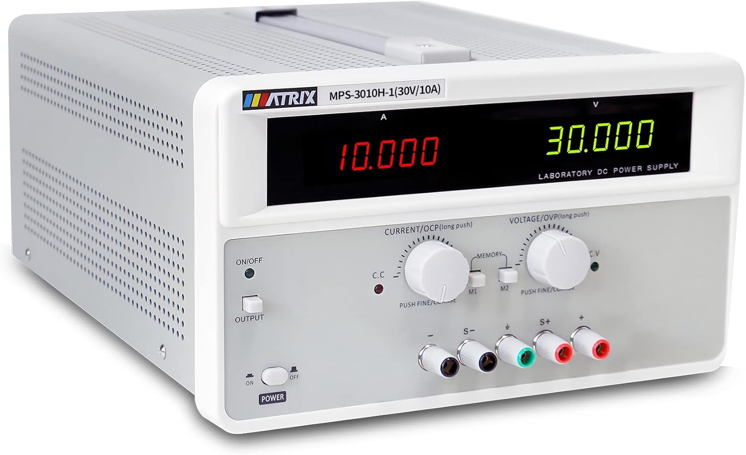
Figure 3.1: Front view of the MPS-3010H-1FBM power supply, showing the digital displays and control knobs.
3.1 Front Panel Description

Figure 3.2: Detailed view of the front panel with labels for each control and display element.
- Current Display Window: Shows the output current in Amperes (A).
- Voltage Display Window: Shows the output voltage in Volts (V).
- Output Switch Menu Function Key: Toggles the output on/off.
- Current Regulation Knob (OCP Setting): Adjusts the output current limit. Push for fine/coarse adjustment. Long push for OCP setting.
- Voltage Regulation Knob (OVP Setting): Adjusts the output voltage. Push for fine/coarse adjustment. Long push for OVP setting.
- Store/Call Buttons (M1, M2): Used to save and recall preset voltage/current values.
- Instrument Power Switch: Main power switch for the unit.
- Output Terminal Negative Terminal (-): Connects to the negative side of the load.
- Grounding Terminal: For safety grounding.
- Remote Compensation Terminals (S-, S+): Used for remote sensing to compensate for voltage drop across load wires.
- Positive End of Output Terminal (+): Connects to the positive side of the load.
3.2 Rear Panel Description
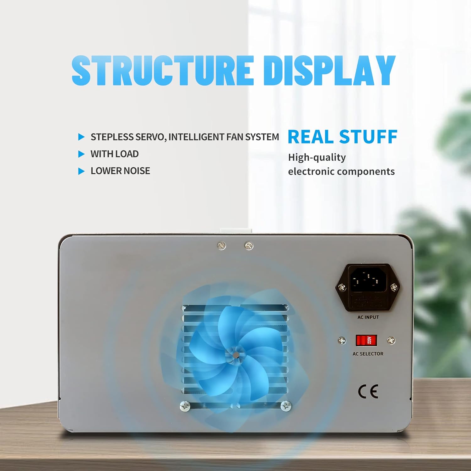
Figure 3.3: Rear panel of the power supply, highlighting the cooling fan and AC input.
- AC Input Socket: For connecting the main power cord.
- AC Selector Switch (110V/220V): Selects the appropriate input voltage.
- Cooling Fan: Provides air circulation for heat dissipation.
4. Setup
Follow these steps to set up your power supply:
- Unpacking: Carefully remove the power supply from its packaging. Inspect for any signs of damage.
- Placement: Place the unit on a stable, level surface with adequate ventilation around the rear cooling fan.
- Input Voltage Selection: Locate the AC selector switch on the rear panel. Ensure it is set to match your local mains voltage (110V or 220V). Incorrect setting can damage the unit.

Figure 4.1: AC input and voltage selector switch.
- Power Connection: Connect the provided power cord to the AC input socket on the rear panel and then to a grounded wall outlet.
- Output Cable Connection: Connect the provided banana-to-alligator clip cables to the output terminals (+ and -) on the front panel. The red cable connects to the positive (+) terminal, and the black cable connects to the negative (-) terminal. Ensure connections are secure.

Figure 4.2: Output terminals for connecting load cables.
5. Operating Instructions
5.1 Basic Operation
- Power On: Flip the Instrument Power Switch on the front panel to the 'ON' position. The display will illuminate.
- Set Voltage: Rotate the Voltage Regulation Knob to adjust the desired output voltage. Push the knob for fine adjustment, release for coarse adjustment.
- Set Current Limit: Rotate the Current Regulation Knob to set the maximum output current limit. Push the knob for fine adjustment, release for coarse adjustment. This acts as a current protection threshold.
- Enable Output: Press the Output Switch Menu Function Key to enable the power output. The 'OUTPUT' indicator will light up. The voltage and current displays will show the actual output values.

Figure 5.1: Output ON/OFF switch.
- Connect Load: With the output disabled, connect your load to the output terminals. Ensure correct polarity.
- Monitor Output: The 5-digit displays provide real-time readings of the output voltage and current.

Figure 5.2: High-resolution current display.
- Power Off: Press the Output Switch Menu Function Key to disable the output, then flip the Instrument Power Switch to 'OFF'.
5.2 Memory Function
The power supply allows you to save and recall two sets of voltage and current settings (M1, M2).
- Saving Settings:
- Adjust the Voltage Regulation Knob and Current Regulation Knob to your desired values.
- Press and hold either the M1 or M2 button until a confirmation beep or indicator appears, indicating the settings are saved.
- Recalling Settings:
- Briefly press the M1 or M2 button. The saved voltage and current values will be loaded and displayed.

Figure 5.3: Control knobs and memory function buttons.
5.3 OVP/OCP Settings (Over Voltage/Current Protection)
The unit features adjustable Over Voltage Protection (OVP) and Over Current Protection (OCP) to safeguard connected devices and the power supply itself.
- Setting OVP:
- With the output disabled, long-press the Voltage Regulation Knob. The display will show the current OVP setting.
- Rotate the knob to adjust the OVP threshold. This value should be set slightly above your desired maximum operating voltage.
- Briefly press the knob again to confirm and exit OVP setting mode.
- Setting OCP:
- With the output disabled, long-press the Current Regulation Knob. The display will show the current OCP setting.
- Rotate the knob to adjust the OCP threshold. This value should be set slightly above your desired maximum operating current.
- Briefly press the knob again to confirm and exit OCP setting mode.
6. Maintenance
Proper maintenance ensures the longevity and reliable operation of your power supply.
- Cleaning: Disconnect the power supply from the mains before cleaning. Use a soft, dry cloth to wipe the exterior. Do not use abrasive cleaners or solvents.
- Ventilation: Ensure the ventilation holes and cooling fan on the rear panel are free from dust and obstructions. Periodically clean with compressed air if necessary.
- Storage: When not in use for extended periods, store the power supply in a dry, dust-free environment.

Figure 6.1: Heat dissipation holes for optimal cooling.
7. Troubleshooting
Refer to this section for common issues and their solutions.
| Problem | Possible Cause | Solution |
|---|---|---|
| No power when switched on | Power cord not connected; AC selector switch incorrect; Blown fuse | Check power cord connection; Verify AC selector switch setting; Replace fuse (refer to qualified personnel) |
| No output voltage/current | Output switch is OFF; OVP/OCP triggered; Load disconnected or faulty | Press the Output switch; Check OVP/OCP settings and reset if necessary; Verify load connection and functionality |
| Output voltage/current unstable | Poor load connection; Overheating; Internal fault | Check load connections; Ensure adequate ventilation; Contact support if problem persists |
| Fan not running | Unit not under load/not hot enough (intelligent fan control); Fan fault | Fan operates based on temperature; If unit is hot and fan is off, contact support |
8. Specifications
Technical specifications for the MPS-3010H-1FBM model:
- Model: MPS-3010H-1FBM
- Output Voltage: 0-30V (Adjustable)
- Output Current: 0-10A (Adjustable)
- Output Wattage: 300 Watts
- Voltage Accuracy: ≤0.01%+10mV
- Current Accuracy: ≤0.1%+10mA
- Display: 5-Digit LED
- Input Voltage: 110V/220V AC (Switchable)
- Cooling Method: Air (Intelligent Fan Control)
- Fan Count: 1
- Item Weight: 29 pounds
- Package Dimensions: 17 x 14 x 10 inches

Figure 8.1: Product dimensions (approximate).
9. Warranty and Support
The MATRIX MPS-3010H-1FBM Adjustable Linear DC Power Supply comes with a 3-year warranty from the date of purchase. This warranty covers defects in materials and workmanship under normal use.
For technical support, warranty claims, or service inquiries, please contact MATRIX customer service. Refer to the official MATRIX website or your purchase documentation for contact details.
Related documentsMPS-3010H-1FBM


Ask a question about this manual
Ask about setup, troubleshooting, compatibility, parts, safety, or missing instructions. Manuals+ will review the question and use this page’s manual context to help answer it.