
1. Introduction
This manual provides detailed instructions for the operation and maintenance of your GoolRC Microzone MC6C 2.4GHz 6-channel remote control system, including the MC6C transmitter and MC6RE receiver. This system is designed for various RC models such as airplanes, drones, multirotors, helicopters, cars, and boats.

Figure 1: GoolRC Microzone MC6C Transmitter and MC6RE Receiver. This image shows the main components of the remote control system, including the 6-channel transmitter and the compact MC6RE receiver.
2. Key Features
- Versatile Application: Suitable for RC boats, cars, and multicopters.
- Advanced System: Adopts 2.4G S-FHSS system with a maximum of 6 channels.
- Customizable Controls: Fully assignable control switches, knobs, sticks, and digital trims.
- Low-Voltage Warning: Provides a warning when battery voltage drops below 8.4V (indicated every 500ms).
- Extended Range: Approximately 800m control distance ensures long-range and anti-interference performance.
3. Package Contents
Verify that all items are present in the package:
- 1 x MC6C Transmitter (MODE 1)
- 1 x MC6RE Receiver
4. Specifications
4.1 Transmitter (MC6C)
| Feature | Detail |
|---|---|
| Model | MC6C |
| System | 2.4G S-FHSS System |
| Channels | 6 Channels |
| Frequency | 2.400GHz to 2.483GHz |
| Transmission Power | ≤100mW |
| Working Current | ≤120mA |
| Encoding | PCM1024 |
| Power Supply | 4 * AA Battery (not Included) |
| Control Distance | About 800m |
| Low-voltage Warning | YES |
4.2 Receiver (MC6RE)
| Feature | Detail |
|---|---|
| Model | MC6RE |
| Channels | 6 Channels |
| Power Supply | 4.8-6V |
| Decoding Way | 1024 PPM/PCMS |
| System | 2.4G S-FHSS System |
| Size | 45 * 23 * 13mm (Antenna Excluded) |

Figure 2: MC6RE Receiver Pinout Diagram. This diagram illustrates the various signal and power connections on the MC6RE receiver, including SBUS and PWM signals, and positive/negative electrodes.
5. Setup Guide
5.1 Battery Installation (Transmitter)
- Locate the battery compartment on the back of the MC6C transmitter.
- Open the battery compartment cover.
- Insert four (4) AA batteries, ensuring correct polarity (+/-) as indicated inside the compartment.
- Close the battery compartment cover securely.
5.2 Receiver Connection
Connect the MC6RE receiver to your RC model's flight controller or servos according to the model's specific wiring diagram. Refer to Figure 2 for the receiver's pinout. Ensure correct power supply (4.8-6V) to the receiver.
5.3 Binding (Frequency Alignment)
To establish communication between the transmitter and receiver, a binding process is required:
- Ensure the MC6C transmitter is powered OFF.
- Power on the MC6RE receiver.
- On the MC6RE receiver, locate and press the 'BIND' button.
- While holding the 'BIND' button, power on the MC6C transmitter.
- Observe the LED indicator on the receiver. A solid light typically indicates a successful bind. Release the 'BIND' button once the connection is established.
- Turn off both the transmitter and receiver, then power them on again in the normal sequence (transmitter first, then receiver) to confirm the bind.
6. Operating Instructions
6.1 Powering On/Off
- To power on the transmitter, slide the power switch to the 'ON' position.
- To power on the receiver, ensure it is connected to a power source (e.g., flight controller, ESC with BEC).
- Always power on the transmitter first, then the receiver. When powering off, power off the receiver first, then the transmitter.
6.2 Basic Controls (Mode 1)
The MC6C transmitter is configured for Mode 1 operation. Familiarize yourself with the stick assignments:
- Right Stick: Controls Throttle (vertical movement) and Rudder (horizontal movement).
- Left Stick: Controls Aileron (horizontal movement) and Elevator (vertical movement).
Additional switches and knobs are assignable for auxiliary functions (e.g., flaps, landing gear, flight modes) depending on your model's setup.

Figure 3: MC6C Transmitter Size Comparison. This image compares the dimensions of the MC6C transmitter to a similar model, highlighting its compact and portable design.
6.3 Control Distance and Anti-Interference
The system offers an approximate control distance of 800 meters, providing reliable long-range operation. The 2.4G S-FHSS system is designed to minimize interference, ensuring stable control.
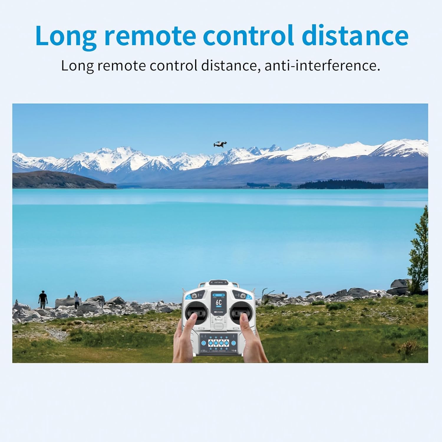
Figure 4: Long Remote Control Distance Demonstration. This image visually represents the extensive control range of the system, showing a remote-controlled aircraft operating at a significant distance from the user.
6.4 Loss of Control Protection
The system incorporates a loss of control protection feature. If the receiver loses signal from the transmitter (e.g., due to range exceeding or transmitter power-off), it will automatically return to a pre-set runaway protection value. This helps protect your model from damage by initiating a failsafe action (e.g., throttle cut, return to home, or holding last command, depending on model configuration).

Figure 5: Loss of Control Protection Feature. This image illustrates the safety mechanism that activates when the receiver loses signal, showing the transmitter and receiver with a protective shield icon.
6.5 Wide Application
The GoolRC Microzone MC6C system is highly versatile and can be used with a wide range of RC models, including:
- RC Airplanes
- RC Drones / Multicopters
- RC Helicopters
- RC Cars
- RC Boats
- Other multi-axle vehicles

Figure 6: Wide Application of MC6C System. This image demonstrates the versatility of the remote control system by showing various RC models it can control, such as cars, boats, airplanes, and drones.
6.6 Compatibility
The MC6C transmitter is compatible with standard MC6RE-V2 and MC7RB-V2 receivers, as well as older models like MC6RE, E6R-E, MC7RB, and MC9002.

Figure 7: Compatibility with Old and New Receivers. This image displays various compatible receiver models, indicating the broad compatibility of the MC6C transmitter.
7. Maintenance
- Keep the transmitter and receiver clean and free from dust and moisture. Use a soft, dry cloth for cleaning.
- Avoid exposing the components to extreme temperatures, direct sunlight, or corrosive materials.
- Remove batteries from the transmitter if it will not be used for an extended period to prevent leakage.
- Regularly inspect all cables and connectors for signs of wear or damage.
- Store the system in a safe place to prevent physical damage.
8. Troubleshooting
| Problem | Possible Cause | Solution |
|---|---|---|
| Transmitter not powering on. | Dead or incorrectly installed batteries. | Replace batteries with fresh ones, ensuring correct polarity. |
| Receiver not responding to transmitter. | Not bound, out of range, or interference. | Perform binding process again. Ensure transmitter and receiver are within range. Check for strong interference sources. |
| Erratic control or signal loss. | Low transmitter battery, excessive distance, or environmental interference. | Check transmitter battery level. Operate within specified range. Avoid areas with high electromagnetic interference. |
| Low-voltage warning on transmitter. | Transmitter battery voltage is low. | Replace or recharge transmitter batteries immediately. |
9. Warranty and Support
For warranty information and technical support, please refer to the GoolRC official website or contact your retailer. Keep your purchase receipt as proof of purchase for warranty claims.
Manufacturer: GoolRC
Recommended Age: 14 years and up