VAR TECH LCR Meter V 8222 H Digital Multimeter User Manual
Model: V 8222H
1. Introduction
The VAR TECH V 8222 H is a True RMS LCR Digital Multimeter designed for precise electrical measurements. It combines the functions of a multimeter with the capability to measure inductance, capacitance, and resistance (LCR). This device is suitable for a wide range of applications, from basic electrical troubleshooting to advanced electronic circuit analysis. It features a large HD display with backlight, dual fuse protection, and a robust, shockproof construction.
2. Safety Information
Always adhere to the following safety precautions when operating the VAR TECH V 8222 H Digital Multimeter to prevent personal injury or damage to the device:
- Read and understand all instructions in this manual before use.
- Do not exceed the maximum input values specified for each measurement range.
- Ensure the test leads are in good condition and properly connected before making any measurements.
- Do not use the meter if it appears damaged or if the casing is open.
- Exercise extreme caution when working with voltages above 30V AC RMS, 42V peak, or 60V DC. These voltages pose a shock hazard.
- Always disconnect power to the circuit and discharge all high-voltage capacitors before measuring resistance, capacitance, or inductance.
- Replace batteries and fuses only with the specified type and rating.
- Do not operate the meter in explosive gas, vapor, or dusty environments.
3. Product Features
The VAR TECH V 8222 H Digital Multimeter offers a comprehensive set of features for various electrical and electronic testing needs:
- True RMS Measurement: Provides accurate readings for non-sinusoidal AC waveforms.
- High Voltage and Current Capacity: Measures up to 1000V DC / 750V AC and 20A DC / AC.
- LCR Measurement: Dedicated functions for Inductance, Capacitance, and Resistance.
- 2000 Counts HD Display: Large, clear display with backlight for easy readability.
- Transistor Test (hFE): Allows for testing of transistor gain.
- Frequency and Temperature Test: Measures frequency and temperature.
- Continuity and Diode Test: For checking circuit continuity and diode functionality.
- Shockproof Construction: Durable design with a protective case.
- Dual Fuse Protection: Enhanced safety with two fuses.
- Additional Functions: Flashlight, Data Hold, Low Battery Indicator, Auto Power Off, Relative Measurement, Min/Max.

Figure 1: VAR TECH V 8222 H Digital Multimeter showcasing its high precision and various features.
4. Setup
4.1. Battery Installation
The VAR TECH V 8222 H requires four AAA batteries (included). To install or replace batteries:
- Ensure the multimeter is turned off and test leads are disconnected.
- Locate the battery compartment cover on the back of the meter.
- Unscrew the retaining screw(s) and remove the cover.
- Insert four AAA batteries, observing the correct polarity (+ and -) as indicated inside the compartment.
- Replace the battery compartment cover and secure it with the screw(s).

Figure 2: Rear view showing the battery compartment and anti-burn double fuse protection.
4.2. Connecting Test Leads
Connect the test leads to the appropriate input jacks on the multimeter:
- Insert the black test lead into the COM (common) jack.
- For most voltage, resistance, capacitance, inductance, frequency, temperature, and diode/continuity measurements, insert the red test lead into the VΩHz jack.
- For current measurements up to 20A, insert the red test lead into the 20A jack.
- For current measurements up to 200mA, insert the red test lead into the mAμA jack.
5. Operation
5.1. Rotary Switch Functions
The central rotary switch is used to select the desired measurement function. Turn the switch to the corresponding position for the measurement you wish to perform.

Figure 3: The multimeter's front panel with the rotary switch for function selection.
5.2. Voltage Measurement (DC/AC)
To measure voltage:
- Connect the red test lead to the VΩHz jack and the black test lead to the COM jack.
- Turn the rotary switch to the desired DCV (V=) or ACV (V~) range.
- Connect the test probes in parallel across the component or circuit to be measured.
- Read the voltage value on the display.
5.3. Current Measurement (DC/AC)
To measure current:
- Important: Disconnect power to the circuit before connecting the meter in series.
- For currents up to 200mA, connect the red test lead to the mAμA jack. For currents up to 20A, connect the red test lead to the 20A jack. Connect the black test lead to the COM jack.
- Turn the rotary switch to the appropriate DCA (A=) or ACA (A~) range.
- Connect the test probes in series with the circuit.
- Apply power to the circuit and read the current value on the display.
5.4. Resistance Measurement
To measure resistance:
- Ensure the circuit is de-energized and all capacitors are discharged.
- Connect the red test lead to the VΩHz jack and the black test lead to the COM jack.
- Turn the rotary switch to the Ω (Ohms) range.
- Connect the test probes across the component.
- Read the resistance value on the display.
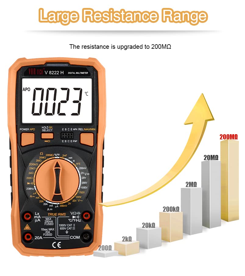
Figure 4: The multimeter supports a large resistance measurement range up to 200 MΩ.
5.5. Capacitance Measurement
To measure capacitance:
- Ensure the capacitor is fully discharged before measurement.
- Connect the red test lead to the VΩHz jack and the black test lead to the COM jack.
- Turn the rotary switch to the capacitance (F) range.
- Connect the test probes across the capacitor.
- Read the capacitance value on the display.
5.6. Inductance Measurement
To measure inductance:
- Ensure the inductor is disconnected from any power source.
- Connect the red test lead to the VΩHz jack and the black test lead to the COM jack.
- Turn the rotary switch to the inductance (H) range.
- Connect the test probes across the inductor.
- Read the inductance value on the display. Note: The meter measures inductance in the range of 2 mH to 20 H.
5.7. Frequency Measurement
To measure frequency:
- Connect the red test lead to the VΩHz jack and the black test lead to the COM jack.
- Turn the rotary switch to the Hz range.
- Connect the test probes across the signal source.
- Read the frequency value on the display.
5.8. Temperature Measurement
To measure temperature:
- Connect the temperature probe to the appropriate input jacks (usually VΩHz and COM, or dedicated temperature jacks if available).
- Turn the rotary switch to the °C/°F range.
- Place the temperature probe on or near the object whose temperature is to be measured.
- Read the temperature value on the display.
5.9. Transistor (hFE) Test
To perform a transistor hFE test:
- Turn the rotary switch to the hFE position.
- Insert the transistor leads (Emitter, Base, Collector) into the corresponding holes in the hFE socket on the meter, ensuring correct NPN or PNP type selection.
- Read the hFE value on the display.
5.10. Diode and Continuity Test
To perform diode or continuity tests:
- Ensure the circuit is de-energized.
- Connect the red test lead to the VΩHz jack and the black test lead to the COM jack.
- Turn the rotary switch to the Diode/Continuity ( ▶ / Ω ) position.
- For diode test, connect the probes across the diode. The display will show the forward voltage drop.
- For continuity test, connect the probes across the circuit. An audible beep indicates continuity (low resistance).
5.11. Special Functions
- Data Hold: Press the 'HOLD' button to freeze the current reading on the display. Press again to release.
- Min/Max: Press the 'MIN/MAX' button to record the minimum and maximum readings. Press again to cycle through Min, Max, and current readings.
- Relative Measurement: Press the 'REL' button to store the current reading as a reference. Subsequent measurements will be displayed as a difference from this reference.
- Flashlight Function: Press and hold the flashlight button for more than 2 seconds to turn the built-in flashlight on or off. This is useful for working in dimly lit areas.

Figure 5: The flashlight function provides illumination for dark environments.
- Auto Power Off (APO): The meter automatically turns off after a period of inactivity to conserve battery life.
6. Maintenance
Proper maintenance ensures the longevity and accuracy of your VAR TECH V 8222 H Digital Multimeter.
- Cleaning: Wipe the meter's casing with a damp cloth and mild detergent. Do not use abrasives or solvents.
- Battery Replacement: Replace batteries when the low battery indicator appears on the display. Refer to Section 4.1 for instructions.
- Fuse Replacement: If the current measurement function stops working, the fuse may need replacement. Refer to the battery compartment for fuse specifications and replacement instructions. Always use fuses with the correct voltage and current rating.
- Storage: If the meter is not used for an extended period, remove the batteries to prevent leakage. Store the meter in a cool, dry place.
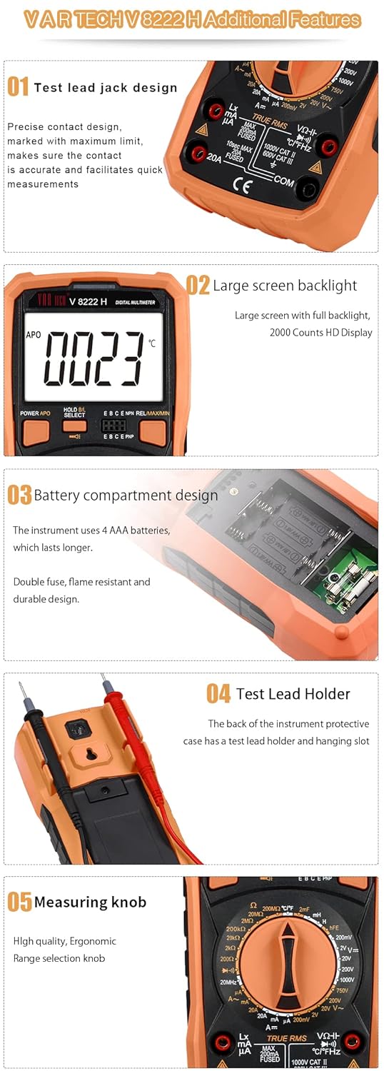
Figure 6: Additional features including the test lead holder on the back for convenient storage.
7. Troubleshooting
If you encounter issues with your multimeter, refer to the following common problems and solutions:
- No Display: Check if the batteries are correctly installed and have sufficient charge. Replace if necessary.
- Incorrect Readings: Ensure test leads are properly connected to the correct jacks and the rotary switch is set to the appropriate function and range. Verify the circuit is de-energized for resistance, capacitance, and inductance measurements.
- Current Measurement Not Working: Check the fuse. If blown, replace it with a fuse of the specified rating.
- Display Shows 'OL' (Overload): The measured value exceeds the selected range. Switch to a higher range or ensure the input is within the meter's capabilities.
8. Specifications
Detailed technical specifications for the VAR TECH V 8222 H Digital Multimeter:
| Specification | Value |
|---|---|
| Brand | VAR TECH |
| Model Number | V 8222H |
| Display | 2000 Counts HD Display with Backlight |
| DC Voltage | Up to 1000V |
| AC Voltage | Up to 750V |
| DC Current | Up to 20A |
| AC Current | Up to 20A |
| Resistance | 200 Ω to 200 MΩ |
| Capacitance | 20 nF to 2 mF |
| Inductance | 2 mH to 20 H |
| Frequency | Yes |
| Temperature | Yes |
| Transistor Test (hFE) | Yes |
| Continuity Test | Yes |
| Diode Test | Yes |
| Power Source | 4 AAA batteries (included) |
| Item Weight | 400 g |
| Product Dimensions (LxWxH) | 18.6 x 9.2 x 5.2 cm |
| Country of Origin | China |
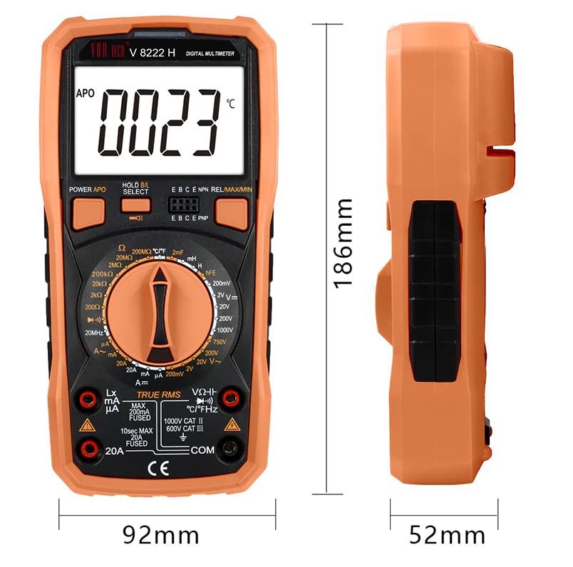
Figure 7: Physical dimensions of the VAR TECH V 8222 H multimeter.
9. Warranty and Support
The VAR TECH V 8222 H Digital Multimeter comes with a 1-year warranty against manufacturing defects. For technical assistance, troubleshooting, or warranty claims, please contact VAR TECH customer support. VAR TECH is committed to providing quality products and dedicated after-sales support.
Video 1: Product overview highlighting features and VAR TECH's commitment to quality and support.
Video 2: Detailed feature presentation of the VAR TECH V 8222 H Digital Multimeter.


