1. Introduction
This manual provides essential information for the safe and effective operation of the BSIDE ACM91 DC Clamp Meter. Please read this manual thoroughly before using the device to ensure proper functionality and to prevent potential hazards. The BSIDE ACM91 is a compact, auto-ranging digital multimeter designed for measuring AC/DC current, AC/DC voltage, resistance, capacitance, frequency, and temperature, featuring True RMS measurement and a V-Alert function.
2. Safety Information
WARNING: To avoid electric shock or personal injury, and to prevent damage to the meter or the equipment under test, follow these safety guidelines:
- Always ensure the meter is in the correct function and range for the measurement.
- Do not apply more than the rated voltage, as marked on the meter, between the terminals or between any terminal and earth ground.
- Use caution when working with voltages above 30V AC RMS, 42V peak, or 60V DC. Such voltages pose a shock hazard.
- Before making current measurements with the clamp, ensure the circuit is de-energized if possible, and always wear appropriate personal protective equipment.
- Inspect test leads for damaged insulation or exposed metal. Replace if damaged.
- Do not operate the meter if it appears damaged or if the case is open.
- When measuring DC current using the clamp, the readings can be influenced by the Earth's magnetic field. To ensure accurate results:
- Zero out the readings before each measurement.
- Hold the meter in the same orientation when taking readings after zeroing. Avoid tilting, twisting, or rotating it, as changes in orientation can cause false readings due to varying magnetic field strengths.
- Measure the DC current within 3 seconds for optimal accuracy.
- The meter conforms to IEC-61010-1, IEC-61010-2-030, IEC-61010-2-032, IEC-61010-2-033 standards. Over-voltage protection class CAT III 300V, CAT II 600V, pollution degree II.
3. Product Overview
3.1 Components and Accessories
The image below illustrates the BSIDE ACM91 DC Clamp Meter along with its standard accessories.

Image 1: The BSIDE ACM91 DC Clamp Meter, including test leads, thermocouple, carrying case, and screwdriver.
3.2 Key Features
- 1mA AC/DC Current Resolution: Capable of measuring currents as low as 1mA via the clamp jaws, ideal for detecting parasitic draws.
- Microampere (µA) Measurement: Measures microamps (minimum 0.1µA) using the test terminals.
- Dual Line Display: Simultaneously shows two measurement parameters, such as AC voltage/current and frequency, or Celsius and Fahrenheit temperatures.
- Low Impedance (LoZ) Mode: Designed to identify and eliminate ghost or stray voltages, providing more accurate readings in certain circuits.
- V-Alert Function: Non-contact voltage detection that can be activated from any function, enhancing safety and convenience.
- Live Wire Check: Identifies live wires for safety and troubleshooting.
- Auto-Ranging: Automatically selects the appropriate measurement range.
- Auto Power Off: Conserves battery life by automatically shutting down after a period of inactivity.
- Data Hold: Freezes the current reading on the display for easy recording.
- Backlight: Improves visibility in dimly lit environments.
- Back Clip: Allows for convenient attachment to a belt or pocket for portability.
4. Package Contents
Verify that all items listed below are present in your package:
- 1 x BSIDE ACM91 Clamp Meter
- 1 x Pair of Test Leads (Red and Black)
- 1 x Thermocouple (for temperature measurement)
- 1 x Carrying Case
- 1 x Screwdriver
- 1 x User Manual
Note: Batteries (2 x 1.5V AAA) are not included due to aviation security regulations.
5. Setup
5.1 Battery Installation
- Locate the battery compartment on the back of the meter.
- Use the provided screwdriver to open the battery compartment cover.
- Insert two 1.5V AAA batteries, observing the correct polarity (+/-).
- Replace the battery compartment cover and secure it with the screw.
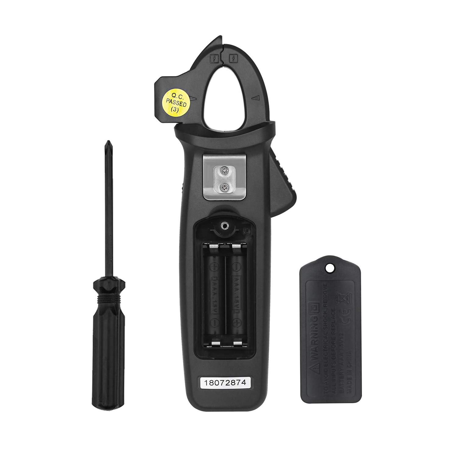
Image 2: Rear view of the BSIDE ACM91 showing the battery compartment and screwdriver.
5.2 Connecting Test Leads
For measurements requiring test leads (voltage, resistance, capacitance, temperature, microamps):
- Insert the red test lead into the 'INPUT' terminal.
- Insert the black test lead into the 'COM' (common) terminal.
6. Operating Instructions
6.1 Power On/Off
Press the Power button to turn the meter on or off.
6.2 Function Selection
Rotate the central dial to select the desired measurement function (e.g., AC/DC current, voltage, resistance, etc.).
6.3 Specific Measurement Modes
- AC/DC Current Measurement (via Jaws):
Select the current measurement mode. Open the clamp jaws and enclose a single conductor. The display will show the current reading. Remember the DC current measurement precautions mentioned in Section 2. The meter offers 1mA resolution for precise current detection.
Image 3: The BSIDE ACM91 measuring DC current on a car battery cable.
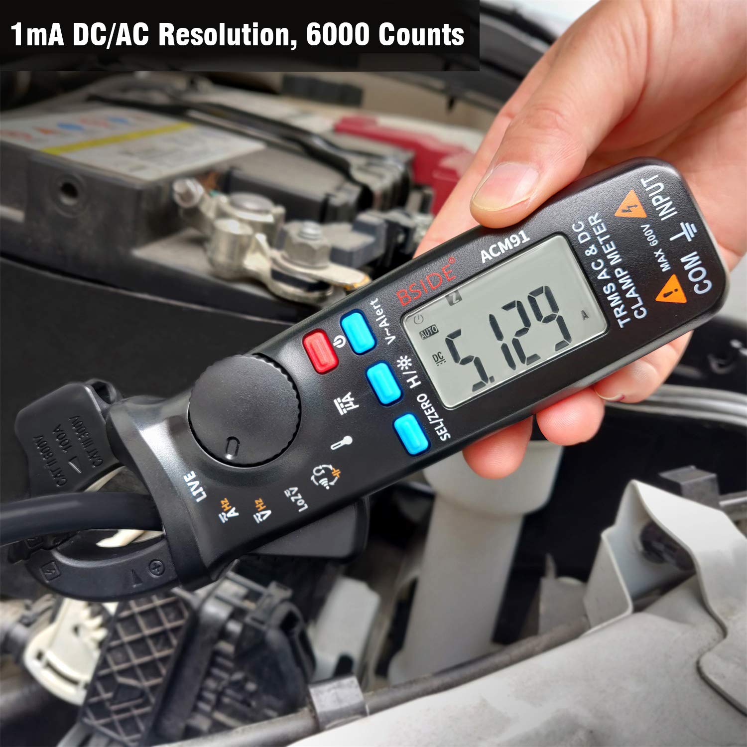
Image 4: The meter displaying a current reading, highlighting its 1mA AC/DC resolution.
- Microampere (µA) Measurement (via Terminals):
Connect the test leads to the circuit in series. Select the µA function. The meter can measure down to 0.1µA. - AC/DC Voltage Measurement:
Connect the test leads in parallel to the circuit or component. Select the AC V or DC V function. - V-Alert (Non-Contact Voltage Detection):
Activate the V-Alert function (often indicated by a specific button or dial position). Hold the meter near a conductor. If voltage is detected, the meter will provide an audible and/or visual indication. This function can be activated from any measurement mode.
Image 5: The V-Alert function detecting voltage near an electrical panel, indicated by a red display and signal waves.
- Live Wire Check:
Select the Live function. Use one test lead (typically the red one) to touch the conductor. The meter will indicate if the wire is live.
Image 6: The meter performing a live wire check on an electrical circuit, showing a red display.
- Frequency Measurement:
Can be measured via test leads or by the clamp jaws (for current frequency). Select the Hz function. - Temperature Measurement:
Connect the thermocouple to the meter's terminals. Select the temperature function. The meter supports both Celsius and Fahrenheit. - Resistance and Continuity Measurement:
Connect test leads across the component. Select the Ohm (Ω) function. For continuity, if resistance is less than 30Ω, the beeper will sound. - Capacitance Measurement:
Ensure the capacitor is discharged before connecting test leads. Select the capacitance function. - Low Impedance (LoZ) Voltage Measurement:
Select the LoZ function. This mode helps in detecting and eliminating ghost voltages.
6.4 Data Hold (H/*)
Press the H/* button to freeze the current reading on the display. Press again to release.
6.5 Backlight
Press and hold the H/* button to activate or deactivate the backlight.
6.6 Dual Line Display
The meter's display can show two parameters simultaneously, such as voltage and frequency, or temperature in Celsius and Fahrenheit. This feature enhances efficiency during measurements.
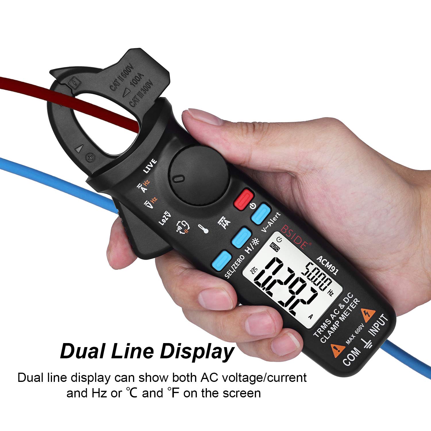
Image 7: The meter's display showing two readings simultaneously, such as current and frequency.
6.7 Back Clip Usage
The integrated back clip allows the meter to be conveniently attached to a belt or pocket, improving portability and accessibility during work.

Image 8: The BSIDE ACM91 attached to a user's belt using its back clip.
7. Maintenance
7.1 Cleaning
Wipe the meter's case with a damp cloth and mild detergent. Do not use abrasives or solvents. Ensure the meter is completely dry before use.
7.2 Battery Replacement
When the low battery indicator appears on the display, replace the batteries as described in Section 5.1. Remove batteries if the meter will not be used for an extended period.
8. Troubleshooting
- No Display: Check battery installation and ensure batteries are not depleted.
- Inaccurate Readings: Verify correct function selection, proper test lead connection, and adherence to measurement procedures (especially for DC current). Ensure the meter is not exposed to strong electromagnetic fields.
- Continuity Beeper Not Sounding: Check if the resistance is above 30Ω.
- Meter Not Responding: Try turning the meter off and on again. If issues persist, replace batteries.
9. Specifications
| Parameter | Range | Resolution | Accuracy |
|---|---|---|---|
| Display | 6000 Counts | ||
| DC Current | 6A/60A/100A | 0.001A/0.01A/0.1A | ±(3.0%+5 counts) |
| DC Current (µA) | 0-200µA | 0.1µA | ±(0.8%+5 counts) |
| AC Current | 6A/60A/100A | 0.001A/0.01A/0.1A | ±(2.5%+5 counts) |
| DC Voltage | 6V/60V/600V | 0.001V/0.01V/0.1V | ±(1.0%+3 counts) |
| AC Voltage | 6V/60V/600V | 0.001V/0.01V/0.1V | ±(1.0%+3 counts) |
| Low Impedance (LoZ) | Max 600V | 0.1V | |
| Resistance | 600Ω/6kΩ/60kΩ/600kΩ/6MΩ | 0.1Ω/0.001KΩ/0.01KΩ/0.1KΩ/0.001MΩ | ±(1.0%+3 counts) |
| Resistance | 60MΩ | 0.01MΩ | ±(1.2%+20 counts) |
| Capacitance | 600µF/6000µF | 0.1µF/1µF | ±(4.0%+3 counts) |
| Frequency | 60Hz/1000Hz | 0.1Hz/1Hz | ±(1.0%+5 counts) |
| Frequency (by jaws) | 60Hz/1000Hz | 0.1Hz/1Hz | ±(1.0%+5 counts) |
| Temperature | -20℃~500℃ | 1℃/2℉ | ±(2.0%+2 counts) |
| Jaw Capacity | 20mm | ||
| Power | 1.5V (AAA) x 2 | ||
| Size | 179 x 67 x 36 mm | ||
| Weight | 137g | ||


