
1. Introduction
This manual provides essential instructions for the safe and efficient operation, setup, and maintenance of your LCRHLCNC 1.5KW 110V Square Air Cooled Spindle Motor Kit. Please read this manual thoroughly before installation and use to ensure proper function and longevity of the equipment.
The kit includes:
- 1x 110V/1.5KW Square Air Cooled Spindle Motor
- 1x 1.5KW/110V YL Variable Frequency Drive (VFD)
- 7x ER11 Collets (1-7mm)

Figure 1.1: LCRHLCNC 1.5KW 110V Spindle Motor Kit, showing the spindle motor, VFD, and ER11 collets.
2. Safety Information
WARNING: Improper installation or operation can lead to serious injury or equipment damage. Always follow safety guidelines.
- Ensure all electrical connections are made by a qualified electrician and comply with local electrical codes.
- Always disconnect power before performing any maintenance, installation, or troubleshooting.
- Wear appropriate personal protective equipment (PPE), including eye protection, during operation.
- Keep hands and loose clothing away from rotating parts. The spindle operates at high speeds (up to 24000 RPM).
- Ensure the spindle motor is securely mounted before operation.
- Do not operate the spindle motor if any part is damaged or malfunctioning.
- Provide adequate ventilation for the VFD and spindle motor to prevent overheating.
- The VFD contains high voltage components. Do not open the VFD enclosure unless you are a qualified technician.
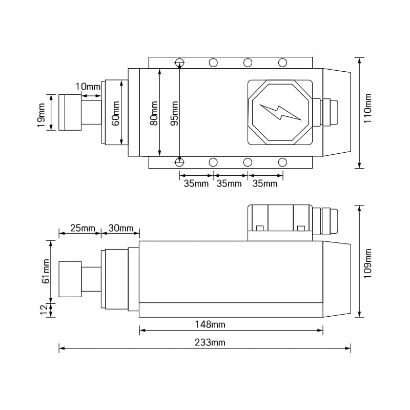
Figure 2.1: Spindle motor with a "DANGER: CUT, Keep hands away" warning label, emphasizing the high-speed rotation and potential hazards.
3. Setup and Installation
3.1 Unpacking and Inspection
Carefully unpack all components. Inspect for any signs of shipping damage. Report any damage to your supplier immediately.
3.2 Mounting the Spindle Motor
Mount the square spindle motor securely to your CNC machine's Z-axis or gantry. Ensure the mounting surface is flat and rigid to minimize vibration. Refer to the dimensional drawing for mounting hole locations and overall dimensions.

Figure 3.1: Dimensional drawing of the spindle motor, providing key measurements for mounting and integration into a CNC system.
3.3 Electrical Connections
The VFD (Variable Frequency Drive) controls the spindle motor. Proper wiring is critical for safe and correct operation.
- Power Input to VFD: Connect your 110V AC power supply to the VFD's input terminals (L, N, and Ground). The VFD supports single-phase input.
- VFD to Spindle Motor: Connect the VFD's three-phase output (U, V, W) to the corresponding terminals on the spindle motor. Ensure correct phase sequence.
- Grounding: Ensure both the VFD and the spindle motor are properly grounded to prevent electrical hazards.
- Brake Resistance (Optional): If using an external brake resistance, connect it to the designated terminals on the VFD.
IMPORTANT: The manufacturer states, "don't need to set VFD, please use it directly." This implies the VFD comes pre-configured for this spindle motor. Do not attempt to change VFD parameters unless you are experienced and understand the implications.

Figure 3.2: Wiring diagram illustrating the connections between the 110V power supply, the VFD (YL620-A), and the spindle motor, including ground lead and optional brake resistance connections.
3.4 Collet Installation
The kit includes 7 ER11 collets ranging from 1mm to 7mm. Select the appropriate collet for your tool shank diameter.
- Insert the collet into the collet nut.
- Thread the collet nut onto the spindle shaft.
- Insert the cutting tool into the collet.
- Tighten the collet nut firmly using a collet wrench. Do not overtighten.
4. Operating Instructions
4.1 Initial Power-Up
After ensuring all connections are secure and correct, apply power to the VFD. The VFD display should illuminate.
4.2 Spindle Operation
The VFD controls the spindle motor's speed and direction. As per manufacturer instructions, the VFD is pre-set. Typically, you will control the spindle through your CNC controller, which sends commands to the VFD.
- Speed Range: The spindle motor operates at speeds from 0 to 24000 RPM.
- Frequency: The VFD output frequency range is 0-400Hz.
- Run Out: The spindle features a run out of less than 0.005mm for high precision.
CAUTION: Always start the spindle at a lower RPM and gradually increase to the desired speed. Avoid sudden changes in speed, especially with heavy cutting loads.
4.3 Applications
This spindle motor kit is suitable for engraving and milling various materials, including:
- Wood
- Bamboo
- Normal PCB (Printed Circuit Boards)
- PVC (Polyvinyl Chloride)
- PMMA (Acrylic)
- Plastic
- Duotone board (ABS)
- Other non-metal materials
- Soft metals such as gold, silver, copper, aluminum, and lead.
5. Maintenance
5.1 General Cleaning
Regularly clean the exterior of the spindle motor and VFD to prevent dust and debris buildup, which can hinder cooling and performance. Use a soft, dry cloth. Do not use solvents or abrasive cleaners.
5.2 Spindle Bearings
The spindle motor is equipped with high-quality P4 grade angular contact ball bearings (2x7005C P4 DT, 2x7003C P4 DT). These bearings are designed for high-speed operation and long life. They are typically sealed and require no user lubrication.

Figure 5.1: Cutaway illustration showing the internal high-quality P4 grade bearings within the spindle motor, designed for high-speed and precision.
5.3 Air Cooling System
The spindle motor is air-cooled. Ensure the cooling fins and fan (if visible) are free from obstructions to maintain efficient heat dissipation. Proper cooling is essential for spindle longevity and performance.

Figure 5.2: Spindle motor illustrating the air cooling mechanism, highlighting its high temperature resistance capability.
6. Troubleshooting
This section provides basic troubleshooting steps for common issues. For complex problems, consult a qualified technician or contact customer support.
- Spindle Not Rotating:
- Check power supply to the VFD.
- Verify VFD to spindle motor wiring.
- Ensure the VFD is receiving a run command from your CNC controller.
- Check for VFD error codes (refer to VFD manual for specific codes).
- Excessive Vibration or Noise:
- Ensure the spindle motor is securely mounted.
- Check if the cutting tool is properly balanced and securely held in the collet.
- Inspect bearings for damage (unlikely for new units, but possible after extended use or impact).
- Overheating:
- Ensure adequate airflow around the spindle motor and VFD.
- Clean any dust or debris from cooling fins.
- Verify ambient temperature is within operating limits.
Note: The VFD is pre-set. If you encounter issues that seem related to VFD parameters, and you are not experienced, it is recommended to contact technical support rather than attempting to modify settings.
7. Specifications
| Component | Specification |
|---|---|
| Spindle Motor Power | 1.5 KW (1.5 Horsepower) |
| Spindle Motor Voltage | 110 Volts (AC) |
| Spindle Speed | 0 - 24000 RPM |
| Frequency | 400 Hz |
| Run Out Accuracy | Less than 0.005mm |
| Bearings | P4 grade (2x7005C P4 DT, 2x7003C P4 DT) |
| Cooling Method | Air Cooled |
| Collet Type | ER11 |
| Collet Sizes Included | 7 pcs (1mm, 2mm, 3mm, 4mm, 5mm, 6mm, 7mm) |
| VFD Model | YL620-A |
| VFD Input Voltage | 110V (Single Phase or Three Phase) |
| VFD Output Frequency | 0 - 400 Hz |
| VFD Output Current | 14A |
| VFD Drive Capacity | 4.0 KVA |
| Total Item Weight | 5.4 Kilograms |
| Package Dimensions | 40.28 x 30.81 x 19.61 cm |
| Manufacturer | Lishui Hengli Automation Technology Co., Ltd |
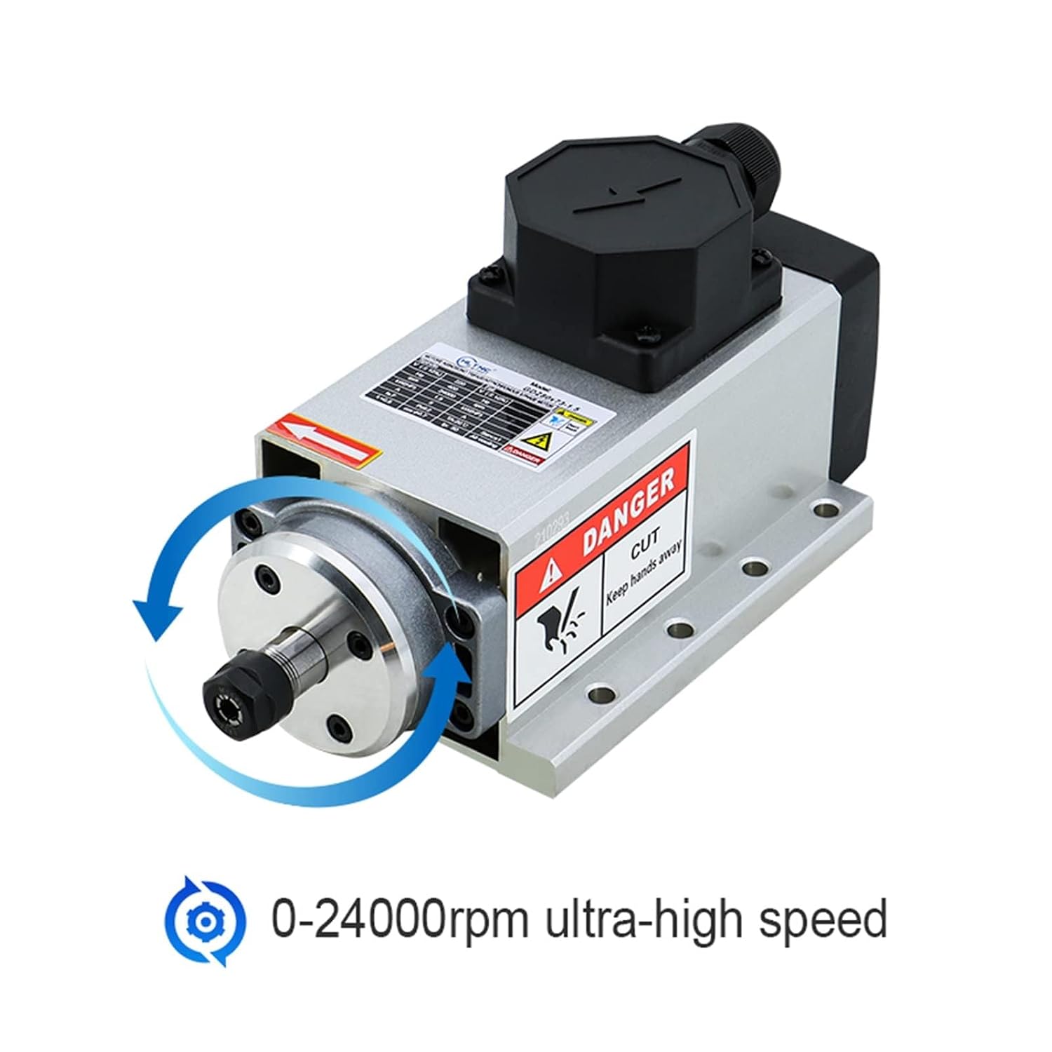
Figure 7.1: Detailed specifications for the YL620-A Variable Frequency Drive, including model, power, input voltage, output current, and dimensions.
8. Warranty and Support
For warranty information and technical support, please refer to the documentation provided with your purchase or contact your vendor directly. Keep your purchase receipt as proof of purchase.