
Introduction
This manual provides detailed instructions for the installation, operation, and maintenance of the ROGER TECHNOLOGY MC775 Magnetic Limit Switch Kit. This kit is designed to work seamlessly with ROGER TECHNOLOGY control units H70/103AC, H70/104AC, B70/1DC, and B70/1DCHP, ensuring precise control over gate opener movements. Please read this manual thoroughly before proceeding with installation or operation.
Important Safety Information
- Qualified Personnel: Installation and maintenance must be performed by qualified personnel only.
- Power Disconnection: Always disconnect power to the control unit before performing any installation, maintenance, or troubleshooting.
- Electrical Safety: Ensure all electrical connections comply with local regulations and standards.
- Moving Parts: Be aware of moving gate parts during testing and operation. Keep hands and loose clothing clear.
- Original Parts: Use only original ROGER TECHNOLOGY spare parts and accessories.
Package Contents
Verify that all components are present and undamaged before beginning installation.
- Magnetic Limit Switch (MC775)
- Mounting Brackets
- Magnets (2 units)
- Fasteners (screws, nuts, washers)
- Instruction Manual (this document)
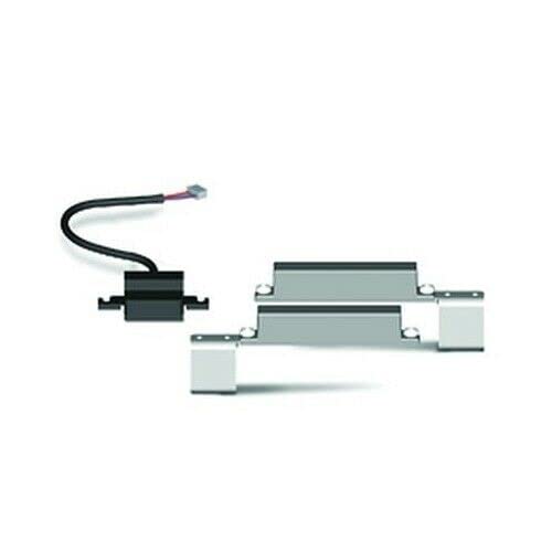
Figure 1: Components of the MC775 Magnetic Limit Switch Kit. Includes the main switch unit, two magnets, and mounting hardware.
Installation Guide
1. Preparation
- Disconnect Power: Ensure the main power supply to the gate opener control unit is disconnected before starting.
- Identify Mounting Location: Determine the optimal position for the magnetic limit switch and magnets on the gate and its structure. The switch should be mounted on the fixed part of the gate structure, and the magnets on the moving gate leaf.
- Tools Required: Gather necessary tools including a drill, screwdriver set, measuring tape, and level.
2. Mounting the Magnetic Limit Switch
- Position the MC775 limit switch unit on the gate's fixed support structure. Ensure it is level and securely fastened using the provided mounting brackets and screws.
- The switch should be positioned such that the magnets, when mounted on the gate leaf, will pass directly over the sensor area of the switch at the desired open and closed positions.
3. Mounting the Magnets
- Mount one magnet on the gate leaf at the position where the gate should fully open. This magnet will trigger the "open" limit.
- Mount the second magnet on the gate leaf at the position where the gate should fully close. This magnet will trigger the "close" limit.
- Ensure the magnets are aligned with the sensor area of the limit switch and are within the effective sensing range (typically a few millimeters to a centimeter, refer to control unit manual for exact specifications).
4. Wiring the Limit Switch to the Control Unit
Refer to the specific wiring diagram in your ROGER TECHNOLOGY control unit manual (H70/103AC, H70/104AC, B70/1DC, B70/1DCHP) for precise connection points. Generally, the magnetic limit switch will connect to dedicated "OPEN LIMIT" and "CLOSE LIMIT" terminals on the control board.
- Connect the wires from the MC775 switch to the corresponding terminals on the control unit. Pay close attention to polarity if specified.
- Secure all connections and ensure no bare wires are exposed.
5. Initial Testing and Adjustment
- Reconnect Power: Carefully reconnect the main power supply to the control unit.
- Test Gate Movement: Operate the gate manually or via the control unit to observe the interaction between the magnets and the limit switch.
- Adjust Magnet Positions: If the gate does not stop at the desired open or closed positions, adjust the magnet positions slightly until the correct stopping points are achieved. The magnets should trigger the switch precisely at the full open and full closed positions.
- Verify Functionality: Perform several full open and close cycles to ensure consistent and reliable operation of the limit switches.
Operation
Once installed and configured, the MC775 Magnetic Limit Switch Kit operates automatically in conjunction with your ROGER TECHNOLOGY control unit. The magnets mounted on the gate leaf will activate the switch when the gate reaches its fully open or fully closed position, signaling the control unit to stop the motor. This ensures precise and repeatable gate positioning.
- The "open" magnet triggers the switch to signal the gate is fully open.
- The "close" magnet triggers the switch to signal the gate is fully closed.
- The control unit interprets these signals to manage motor operation and prevent over-travel.
Maintenance
The MC775 Magnetic Limit Switch Kit is designed for low maintenance. However, periodic checks are recommended to ensure optimal performance and longevity.
- Visual Inspection (Monthly): Check the limit switch and magnets for any signs of physical damage, corrosion, or loose mounting.
- Cleanliness: Ensure the area around the limit switch and magnets is free from dirt, debris, or obstructions that could interfere with their operation.
- Wiring Check (Annually): Inspect the wiring connections to the control unit for any signs of wear, fraying, or loose terminals.
- Functionality Test (Quarterly): Manually operate the gate to its full open and closed positions to confirm that the limit switches are activating correctly and stopping the gate precisely.
Troubleshooting
| Problem | Possible Cause | Solution |
|---|---|---|
| Gate does not stop at desired open/closed position. | Magnets are not correctly positioned or aligned with the switch. | Adjust the position of the magnets on the gate leaf until the gate stops precisely. Ensure magnets pass directly over the sensor. |
| Gate over-travels or does not stop at all. | Faulty wiring connection to the control unit; Damaged limit switch; Magnets too far from the switch. | Check all wiring connections for security and continuity. Verify magnet proximity. If issues persist, the switch may need replacement. |
| Intermittent stopping. | Loose wiring; Debris obstructing the switch/magnet path; Weak magnets. | Inspect wiring for loose connections. Clean the area around the switch and magnets. If magnets are old, consider replacing them. |
If you encounter problems not listed here or if the suggested solutions do not resolve the issue, please contact ROGER TECHNOLOGY technical support or a qualified technician.
Specifications
| Model | MC775 |
| Brand | ROGER TECHNOLOGY |
| Manufacturer | Dieffematic |
| Compatibility | ROGER TECHNOLOGY H70/103AC, H70/104AC, B70/1DC, B70/1DCHP Control Units |
| Type | Magnetic Limit Switch Kit |
| ASIN | B09ZPFWFMC |
Warranty and Support
For warranty information, please refer to the documentation provided with your ROGER TECHNOLOGY control unit or contact your authorized ROGER TECHNOLOGY dealer. Information regarding spare parts availability for the MC775 kit is not explicitly provided in this document; please consult your supplier or ROGER TECHNOLOGY directly for assistance.
For technical support, please visit the official ROGER TECHNOLOGY website or contact their customer service department.