
AMOCAM 520-70W-8
AMOCAM 8-Unit Apartment Video Door Phone Intercom System User Manual
Model: 520-70W-8
1. Introduction
This manual provides detailed instructions for the installation, operation, and maintenance of your AMOCAM 8-Unit Apartment Video Door Phone Intercom System. This system allows residents to see, hear, and speak with visitors at the building entrance, enhancing security and convenience. Please read this manual thoroughly before installation and use to ensure proper functionality and safety.
2. Safety Information
- Ensure all power is disconnected before performing any installation or maintenance.
- Do not expose the outdoor unit to extreme temperatures, direct sunlight for prolonged periods, or excessive moisture.
- Use only the provided power adapters and cables.
- Avoid placing the indoor monitor near heat sources or in areas with high humidity.
- Do not attempt to repair or modify the system components yourself. Contact qualified personnel for service.
- Keep the system away from strong electromagnetic fields.
3. Package Contents
Verify that all items listed below are present in your package:
- 1 x Outdoor Camera Unit
- 8 x Indoor Monitor Units
- 8 x Hanging Plates for Indoor Monitors
- 8 x Power Adapters for Indoor Monitors
- 8 x 4-core/5-core Connection Cables
- 1 x 2-core Connection Cable
- 1 x Bag of Screws and Wall Plugs
- 1 x User Manual (this document)

Figure 3.1: Overview of the AMOCAM 8-Unit Apartment Video Door Phone Intercom System, showing one outdoor unit and eight indoor monitors.
4. Product Overview
4.1 Outdoor Camera Unit
The outdoor unit features an aluminum alloy casing for durability and weather resistance (IP65 rated). It includes a 700 TVL color CMOS camera with built-in 5 LED lights for night vision, a microphone, a speaker, and 8 call buttons, each corresponding to an indoor monitor.
- Camera Resolution: 700 TV Lines
- Camera Type: 1/3 Color CMOS
- Night Vision: Built-in 5 LED lights
- Audio: Built-in microphone and speaker
- Call Buttons: 8 separate buttons for 8 households
- Material: Aluminum alloy, weatherproof (IP65)
- Dimensions: 4.8 x 10.8 x 1.7 inches

Figure 4.1.1: Detailed view of the outdoor camera unit, labeling the microphone, camera, LED lights, aluminum panels, speaker, and call buttons.

Figure 4.1.2: Front view of the outdoor camera unit, highlighting its sleek design and call buttons.

Figure 4.1.3: Back view of the outdoor camera unit, showing mounting points and connection ports.
4.2 Indoor Monitor Unit
Each indoor monitor features a 7-inch TFT LCD color screen with touch-sensitive keys for various functions. It allows for two-way communication with the outdoor unit, monitoring, and door unlocking.
- Display: 7-inch TFT LCD screen (16:9 aspect ratio)
- Resolution: 800 x 480 pixels
- Input Power: AC 100-240V, 50-60Hz
- Output Power: DC 15V/1500mA
- Case Material: ABS Engineering Plastics
- Installation: Surface mounting
- Dimensions: 8.9 x 6.4 x 1.0 inches
- Functions: Door answering, monitoring, unlock, dual-way intercom, volume/brightness/contrast adjustment, 16 doorbell chimes.

Figure 4.2.1: Clear front view of the indoor monitor, displaying its 7-inch screen and touch-sensitive function buttons.
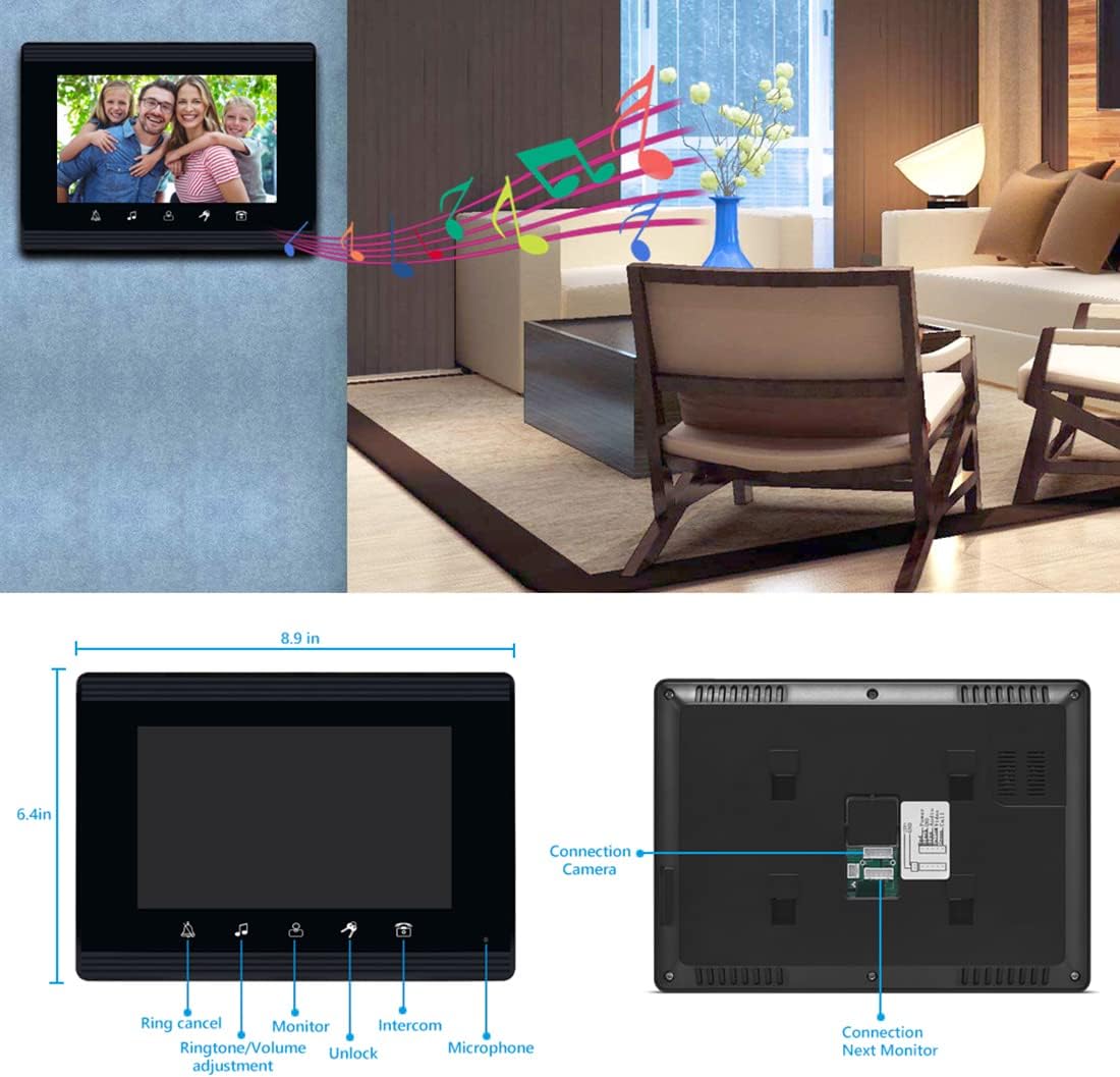
Figure 4.2.2: Front and back view of the indoor monitor, showing its dimensions, touch keys, and connection points for the camera and other monitors.
5. Setup and Installation
Proper installation is crucial for optimal performance. Follow these steps carefully.
5.1 Installation Diagram

Figure 5.1.1: Diagram illustrating the connection of the outdoor unit to multiple indoor units and an optional e-lock within an apartment building.
5.2 Outdoor Camera Unit Installation
- Determine Mounting Location: Choose a location near the entrance, ensuring the camera lens is at a standard height of 145-160 cm from the ground for optimal viewing of visitors.
- Mounting Bracket: Secure the mounting bracket (set iron) to the wall using the provided screws and wall plugs. Ensure it is level and firmly attached.
- Wiring: Route the 4-core/5-core connection cable from the outdoor unit's location to the indoor monitor's location. Connect the wires according to the wiring diagram (refer to Figure 5.4.1).
- Attach Outdoor Unit: Carefully attach the outdoor unit to the mounted bracket, ensuring all cables are properly connected and secured.
5.3 Indoor Monitor Unit Installation
- Mounting Location: Select a convenient indoor location for each monitor, typically near the entrance of each apartment.
- Hanging Plate: Fix the hanging plate to the wall using screws.
- Wiring: Connect the 4-core/5-core cable from the outdoor unit (or previous indoor monitor in a multi-monitor setup) to the indoor monitor. Connect the power adapter to the monitor and a power outlet.
- Hang Monitor: Carefully hang the indoor monitor onto the secured hanging plate.
5.4 Wiring Diagram

Figure 5.4.1: Comprehensive wiring diagram showing connections between the outdoor unit, multiple indoor monitors, power adapters, and an optional electric lock.
Important: Ensure all wiring connections are secure and correctly matched (e.g., power to power, video to video, audio to audio). Incorrect wiring can damage the system.
6. Operating Instructions
6.1 Receiving a Call
- When a visitor presses your apartment's call button on the outdoor unit, your indoor monitor will ring and display the visitor's image.
- To answer the call, touch the Answer icon on the monitor screen. This will initiate two-way audio communication.
- To end the call, touch the Hang Up icon.
6.2 Monitoring
You can view the outdoor area at any time without a visitor initiating a call.
- Touch the Monitor icon on the indoor monitor to activate the outdoor camera feed.
- The screen will display the live video from the outdoor unit.
- Touch the Monitor icon again or wait for the timeout to end monitoring.
6.3 Unlocking the Door
If an electric lock is connected to the system, you can unlock the door remotely.
- During an active call or while monitoring, touch the Unlock icon on the indoor monitor.
- The connected electric lock will momentarily disengage, allowing the visitor to enter.
6.4 Intercom Function (Between Indoor Monitors)
This system supports communication between indoor monitors within the same apartment or building, if configured.
- To call another indoor monitor, touch the Intercom icon and select the desired monitor number (if applicable).
- To adjust the volume, brightness, or contrast, touch the Settings or Menu icon and navigate to the display/audio settings.
Figure 6.4.1: Indoor monitor displaying touch-sensitive icons for ring cancel, ringtone/volume adjustment, monitor, intercom, microphone, and unlock functions.
7. Maintenance
- Cleaning: Use a soft, dry cloth to clean the indoor monitor screen and casing. For the outdoor unit, a damp cloth can be used, but avoid harsh chemicals or abrasive materials.
- Avoid Water: Do not spray water directly onto the units. While the outdoor unit is weatherproof, direct high-pressure water jets should be avoided.
- Cable Inspection: Periodically check all cables for signs of wear or damage. Replace any damaged cables immediately.
- Software Updates: Check the manufacturer's website for any available firmware updates for improved performance or new features.
8. Troubleshooting
| Problem | Possible Cause | Solution |
|---|---|---|
| No image on indoor monitor. |
|
|
| No audio during intercom. |
|
|
| Door unlock function not working. |
|
|
| Outdoor unit night vision not clear. |
|
|
9. Specifications
9.1 Indoor Monitor Specifications
- Display: 7 inch TFT LCD screen (16:9 display)
- Resolution: 800 x 480
- Input Power: AC 100-240V 50 Hz-60 Hz
- Output Power: DC 15V/1500 mA
- Case Material: ABS Engineering Plastics
- Installation: Surface mounting
- Dimensions: 8.9 x 6.4 x 1.0 inches (22.6 x 16.3 x 2.5 cm)
- Control Method: Touch
- Connectivity: Wired
9.2 Outdoor Camera Specifications
- Camera Resolution: 700 TV Lines
- Camera Sensor: 1/3 Color CMOS Camera
- Audio: Built-in microphone and speaker
- Power Adapter: From Monitor, DC15V
- Viewing Angle: (U/D/L/R, degree): 60/35/70/70
- Connection: 4 core/5 core wire (max support 12 monitors)
- Case Material: Aluminum material, weatherproof (IP65)
- Dimensions: 4.8 x 10.8 x 1.7 inches (12.2 x 27.4 x 4.3 cm)
- Special Feature: Night Vision (5 LED lights)
10. Warranty and Support
AMOCAM products are designed for reliability and performance. For warranty information, technical support, or service inquiries, please refer to the contact information provided on the AMOCAM official website or your purchase documentation. Please have your model number (520-70W-8) and purchase date available when contacting support.
Related documents520-70W-8


Ask a question about this manual
Ask about setup, troubleshooting, compatibility, parts, safety, or missing instructions. Manuals+ will review the question and use this page’s manual context to help answer it.