
Introduction
This manual provides essential instructions for the safe and efficient operation, installation, and maintenance of the Mori Seiki MS Type 17 inch metal lathe. Adherence to these guidelines ensures optimal performance and longevity of the machine. Please read this manual thoroughly before operating the lathe.
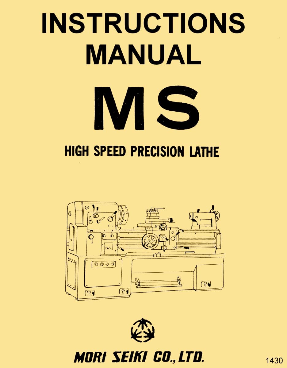
Image: Cover page of the Mori Seiki MS Type 17 Inch Metal Lathe Operator Manual, displaying the title and brand.

Image: First page of the manual's index, listing sections such as Specifications, Installation, Name of Parts, Preparation for Operation, and Lubrication.

Image: Second page of the manual's index, detailing sections including Safety Devices, Sizing Devices, Electric Supply, Braking Device, Removal of Gap, Accuracy Test, and Cutting Speed Diagram.
1. Specifications and Equipment
This section details the standard and optional specifications for the Mori Seiki MS Type 17 inch metal lathe, including its dimensions, power requirements, and operational capacities. It also lists the standard and optional equipment provided with the machine.
1.1 Standard Specification
Outlines the fundamental characteristics and capabilities of the lathe as supplied in its basic configuration.
1.2 Optional Specification
Describes additional features or components that can be integrated to enhance the lathe's functionality.
1.3 Standard Equipment
Lists all accessories and tools included as part of the standard purchase package.
1.4 Optional Equipment
Details supplementary accessories and tools available for separate purchase to expand the lathe's versatility.
2. Installation of Machine
Proper installation is crucial for the safe and accurate operation of the Mori Seiki MS Type 17 inch metal lathe. This section covers the necessary steps from preparing the foundation to the final setup.
2.1 Foundation Work
Instructions for preparing a stable and level foundation to support the lathe, ensuring vibration dampening and structural integrity.
2.2 Unpacking
Guidance on carefully unpacking the machine to prevent damage to components.
2.3 Points of Unloading
Specific instructions for safely unloading the lathe from transport, including recommended lifting points and equipment.
2.4 Outline of Installation
A general overview of the installation process, including positioning, leveling, and securing the machine.
3. Name of Parts
This section provides a comprehensive diagram and list of all major components and controls of the Mori Seiki MS Type 17 inch metal lathe, aiding in identification and understanding their functions.
4. Preparation for Operation
Before commencing operation, specific preparatory steps must be followed to ensure the lathe is ready for use and to prevent damage or injury.
4.1 Power Source Wiring
Detailed instructions for connecting the lathe to the appropriate power supply, including wiring diagrams and safety precautions.
4.2 Identification before Operation
Checks and inspections to perform before starting the machine, such as verifying component integrity and proper lubrication levels.
5. Lubrication
Regular and proper lubrication is essential for the smooth operation and longevity of the Mori Seiki MS Type 17 inch metal lathe. This section outlines the lubrication points and procedures.
5.1 Headstock Forced Lubrication System
Instructions for maintaining the headstock's forced lubrication system, including oil type, fill levels, and inspection intervals.
5.2 Forced Lubrication System for Carriage Sliding Way
Details on lubricating the carriage sliding ways to ensure smooth movement and minimize wear.
5.3 Lubrication of Feed Box
Guidance on lubricating the feed box components to maintain efficient gear operation.
5.4 Lubrication of Other Portions
Information on other critical lubrication points throughout the lathe, including recommended lubricants and application methods.
6. Operation Method
This section provides detailed instructions for various operational procedures of the Mori Seiki MS Type 17 inch metal lathe, from basic spindle control to advanced thread cutting.
6.1 Main Spindle Rotation
How to engage and disengage the main spindle, including safety considerations.
6.2 Change of Spindle Speed
Procedures for adjusting the spindle speed to suit different machining operations and materials.

Image: A detailed view of the lathe's control panel, highlighting the spindle speed change lever and high/low change lever. Also shown are the tailstock handle and clamping lever, with associated operational text.
6.3 Tailstock Operation
Instructions for positioning, clamping, and operating the tailstock for drilling, reaming, and supporting long workpieces.
6.4 Hand Feed Operation
Guidance on using the hand wheels for precise manual control of the carriage and cross slide movements.
6.5 Micrometer Collar
Explanation of the micrometer collar's function and how to use it for accurate depth and diameter adjustments.
6.6 Replacement of Change Gears and Adjustment of Belts
Steps for changing gears to achieve different feed rates and thread pitches, along with instructions for belt tension adjustment.
6.7 Automatic Feed Operation and Feed Speed Change
How to engage and control the automatic feed mechanisms for longitudinal and cross-feed operations, including adjusting feed speeds.
6.8 Thread Cutting Operation
Detailed procedure for setting up and executing thread cutting operations, including gear selection and tool setup.
6.9 Screw (thread) Cutting Indicator
Explanation of the screw cutting indicator's use for accurate thread engagement.
7. Safety Devices
The Mori Seiki MS Type 17 inch metal lathe is equipped with several safety devices designed to protect the operator and the machine. This section describes their function and proper use.
7.1 Automatic Feed Safety Device
Details on the mechanism that prevents overloading of the automatic feed system.
7.2 Change Gear Safety Device
Explanation of the safety feature that prevents accidental engagement of gears during operation or when not properly aligned.
8. Sizing Devices
This section covers devices used for precise control over workpiece dimensions and machine movements.
8.1 Automatic Longitudinal Feed Stop Device
How to set and utilize the device that automatically stops the longitudinal feed at a predetermined position.
8.2 Carriage Micro Stop
Instructions for using the carriage micro stop for fine adjustments and precise positioning.
9. Electric Supply
Understanding the electrical system is vital for safe operation and maintenance. This section details the electrical components and their functions.
9.1 Construction of Electric Supply
Overview of the lathe's electrical circuit and power distribution.
9.2 Order of Operation
The correct sequence for powering on and off the machine to prevent electrical issues.
9.3 Thermal Relay
Explanation of the thermal relay's role in protecting the motor from overheating and how to reset it.
10. Braking Device
The braking system ensures quick and safe stopping of the spindle. This section covers its components and maintenance.
10.1 Friction Pad
Description of the friction pad and its role in the braking mechanism.
10.2 Brake Fluid
Information on the type of brake fluid required and its importance for effective braking.
10.3 Bleeding of Brake System
Procedure for bleeding air from the brake system to maintain optimal performance.
10.4 Bleeding Procedure
Step-by-step guide for performing the brake system bleeding.
10.5 Replacement for Friction Pad
Instructions for replacing worn friction pads to ensure consistent braking efficiency.
10.6 Procedure for Pad Replacement
Detailed steps for safely removing and installing new friction pads.
11. Accuracy Test and Cutting Speed
This section provides information on maintaining the lathe's precision and understanding optimal cutting parameters.
11.1 Removal of Gap
Instructions for adjusting components to eliminate play or gaps that could affect machining accuracy.
11.2 Accuracy Test of Lathe
Procedures for conducting tests to verify the lathe's precision and alignment.
11.3 Cutting Speed Diagram
A diagram or chart illustrating recommended cutting speeds for various materials and operations, optimizing efficiency and tool life.