
1. Product Overview
The Auxbeam 8 Gang Switch Panel BB80 provides a centralized control solution for up to eight 12V/24V auxiliary electrical devices in your vehicle. This system helps organize wiring and simplifies the control of various accessories. The included 4-Pin Wiring Harness Extension facilitates flexible installation and connection.
The switch panel features an automatic dimmable system that adjusts backlight brightness based on ambient light conditions, enhancing visibility and reducing driver distraction.

Figure 1: Auxbeam 8 Gang Switch Panel BB80 and accessories.
2. Specifications

Figure 2: BB80 Product Information.
| Feature | Specification |
|---|---|
| Operation Mode | Automatic |
| Current Rating | 60 Amps (Max) |
| Operating Voltage | 12 Volts - 24 Volts DC |
| Maximum Power (12V) | 600W |
| Maximum Power (24V) | 1200W |
| Contact Type | Normally Open |
| Connector Type | Plug In |
| International Protection Rating | IP54 |
| Number of Positions | 8 |
| Operating Temperature | -40°F to 221°F (-40°C to 105°C) |
| Extension Cable Length | 3.94 Feet |

Figure 3: Fuse box and individual circuit ratings.
Individual Circuit Ratings:
- Circuit 1: 30A
- Circuit 2: 20A
- Circuit 3: 10A
- Circuit 4: 5A
- Circuit 5: 30A
- Circuit 6: 20A
- Circuit 7: 10A
- Circuit 8: 5A
3. Setup and Installation
The Auxbeam 8 Gang Switch Panel BB80 is designed for straightforward installation, minimizing complex wiring. It includes a wear-resistant, plug-and-play wiring harness, fuses, relays, and a temperature protection switch.
3.1 Mounting Options
You can install the switch panel using either the provided mounting bracket or double-sided adhesive tape. This flexibility allows for placement in various locations within your vehicle without requiring large cuts.
3.2 Wiring Connections
The system is designed to keep wires organized within a compact control box. Connect the main power input (DC 12V – DC 24V) to your vehicle's battery, ensuring correct polarity (Battery + and Battery -). The system includes a system failure indicator for diagnostic purposes.
Figure 4: Basic wiring diagram for battery connection.
3.3 Using the 4-Pin Extension Cable
The 4-Pin Wiring Harness Extension (3.94 feet) is designed for transmitting both video and power, making it suitable for extending connections to devices like rearview cameras, DVD players, or monitors. Its plug-and-play design eliminates the need for splicing existing wires.

Figure 5: Auxbeam 4-Pin Extension Cable.

Figure 6: 4-Pin Male & Female Connector features.
The extension cable features braided sleeving for enhanced durability and protection:
- EMI and RF interference protection
- Extends wire lifespan
- Anti-stretch and anti-friction properties
- Flexible design

Figure 7: Braided Sleeving benefits.
The extension cable is compatible with various Auxbeam switch panel models, including BA80, GA80, BB80, GB80, AR-600, AR-800, AR-820, RA80XL, RB80XL, and RA84.

Figure 8: Compatible Auxbeam switch panel models.
4. Operating Instructions
The Auxbeam 8 Gang Switch Panel BB80 allows independent control of up to eight connected accessories. Each switch has an ON/OFF button and a memory function.
4.1 Powering On/Off
Press the individual switch button for the desired circuit to turn the connected accessory on or off. The red indicator light above each switch will illuminate when the circuit is active.
4.2 Automatic Dimmable System
The switch panel is equipped with an automatic dimmable feature. The backlight brightness of the switch panel adjusts automatically based on the ambient light conditions:
- In bright environments (e.g., daytime driving), the panel will be brighter for easier visibility.
- In dark environments (e.g., tunnels or night driving), the panel will dim to reduce glare and minimize impact on the driver's vision.
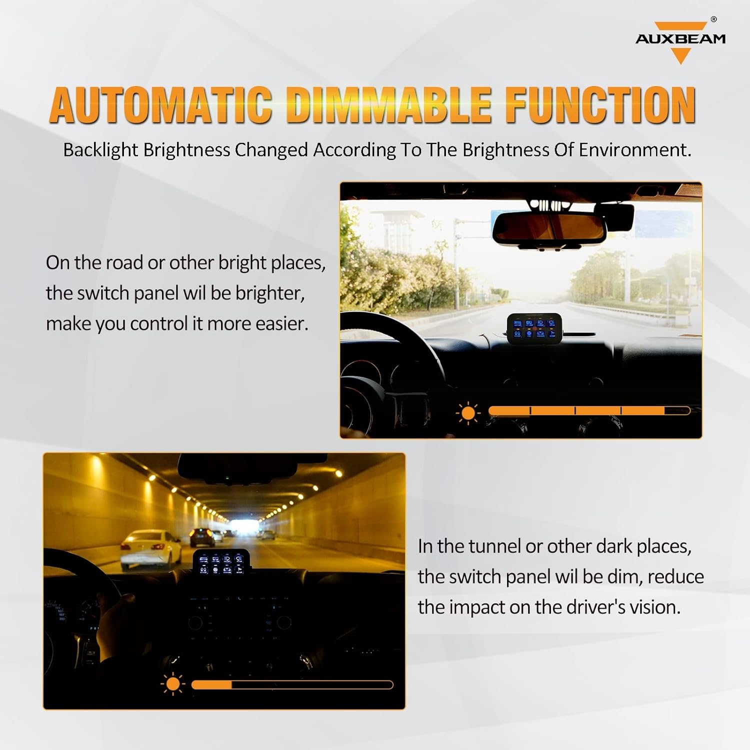
Figure 9: Automatic Dimmable Function in different lighting conditions.
5. Maintenance
To ensure optimal performance and longevity of your Auxbeam 8 Gang Switch Panel BB80 and Wiring Harness Extension, follow these general maintenance guidelines:
- Cleaning: Periodically wipe the switch panel surface with a soft, dry cloth to remove dust and debris. Avoid using harsh chemicals or abrasive cleaners.
- Connection Checks: Regularly inspect all wiring connections to ensure they are secure and free from corrosion. Loose connections can lead to intermittent operation or electrical issues.
- Cable Inspection: Check the wiring harness and extension cable for any signs of wear, fraying, or damage. Replace any damaged cables immediately to prevent electrical hazards.
- Fuse Inspection: If a circuit fails, check the corresponding fuse in the switch assembly. Replace blown fuses with new ones of the correct amperage rating as specified in Section 2.
6. Troubleshooting
If you encounter issues with your Auxbeam 8 Gang Switch Panel BB80, refer to the following troubleshooting steps:
- No Power to Panel:
- Verify that the main power connections to the vehicle battery are secure and correctly polarized.
- Check the main fuse in the wiring harness for continuity.
- Specific Circuit Not Working:
- Ensure the individual switch for that circuit is pressed to the ON position.
- Inspect the fuse for that specific circuit in the switch assembly (refer to Figure 3 for fuse locations and ratings). Replace if blown.
- Check the wiring connection from the switch assembly to the accessory for any disconnections or damage.
- Automatic Dimming Not Functioning:
- Ensure the light sensor on the panel is not obstructed.
- Test the panel in varying light conditions to observe if any adjustment occurs.
- Extension Cable Issues:
- Confirm that the 4-pin connectors are fully seated and locked.
- Inspect the extension cable for any visible damage or kinks.
If problems persist after performing these checks, contact Auxbeam customer support for further assistance.
7. Warranty and Support
For warranty information, product registration, or technical support, please refer to the official Auxbeam website or contact their customer service department directly. Keep your purchase receipt as proof of purchase for any warranty claims.
Auxbeam Customer Support: Please visit the official Auxbeam website for the most current contact information and support resources.