1. Overview
The DAOKAI TCA9548A IIC Multiplexer Breakout Board is designed to expand I2C communication capabilities. The standard I2C communication protocol allows multiple I2C devices to communicate on the same bus, provided each device has a unique I2C address. However, when multiple devices share the same address, direct connection is not possible.
This I2C multiplexer addresses this limitation by enabling communication with up to 8 I2C devices that may share the same address, all connected to a single I2C bus. The multiplexer communicates with a microcontroller using the I2C protocol, allowing you to select which of the 8 I2C buses on the multiplexer you wish to address. Channel selection is achieved by sending a single byte to the multiplexer with the desired output port number.

Figure 1: Conceptual diagram of the TCA9548A I2C Multiplexer connecting multiple I2C devices.
2. Features
- 8 Bidirectional Translating Switches: Allows communication with up to 8 I2C interfaces on one expander, controlled via the I2C bus. This enables connecting 8 devices with the same address to a single I2C port.
- Active-Low Reset Input: Provides a dedicated reset pin for reliable operation.
- Three Address Pins: Supports up to 8 TCA9548A devices on the same I2C bus, allowing for extensive I2C network expansion.
- Channel Selection via I2C Bus: Easily select the desired I2C channel by sending a single byte command.
- Wide Operating Voltage Range: Operates from 1.65V to 5.5V, compatible with various microcontrollers and systems.
- 5V Tolerant Pins: Ensures compatibility and protection when interfacing with 5V systems.
- IIC Bus and System Management Bus Compatibility: Seamless integration into existing I2C and system management bus environments.
- Hot Insertion Support: Allows for connection and disconnection of devices without powering down the system.
- Low Standby Current: Efficient power consumption.
- No Glitch Pulse on Power-On: Ensures stable startup without unintended signals.
- Voltage Level Translation: Supports flat conversion between 1.8V, 2.5V, 3.3V, and 5V buses.
- Cascading Capability: Up to 8 expanders can be cascaded within addresses 0x70-0x77, allowing connection of up to 64 devices with the same I2C address.

Figure 2: Key features of the TCA9548A I2C Multiplexer Breakout Board.
3. Specifications
| Parameter | Value |
|---|---|
| Working Voltage | 1.65V ~ 5.5V |
| IIC Clock Frequency | 0 ~ 400KHz |
| Working Environment Temperature | -40℃ ~ 85℃ |
| Small Board Size | 31.5 x 21.4 mm (1.24 x 0.84 inches) |
| Mounting Holes | Two M3 mounting holes |
| Default I2C Address | 0x70 (Configurable within 0x70 ~ 0x77) |
| Item Weight | 20 g |
| Product Dimensions | 2.14 x 2.14 x 2.14 cm |
| Number of Poles | 8 |

Figure 3: DAOKAI TCA9548A board with key parameters highlighted.

Figure 4: Physical dimensions of the TCA9548A I2C Multiplexer Breakout Board.
4. Pinout and Circuit Diagram
Understanding the pinout and internal circuit is crucial for proper integration and operation of the TCA9548A multiplexer.
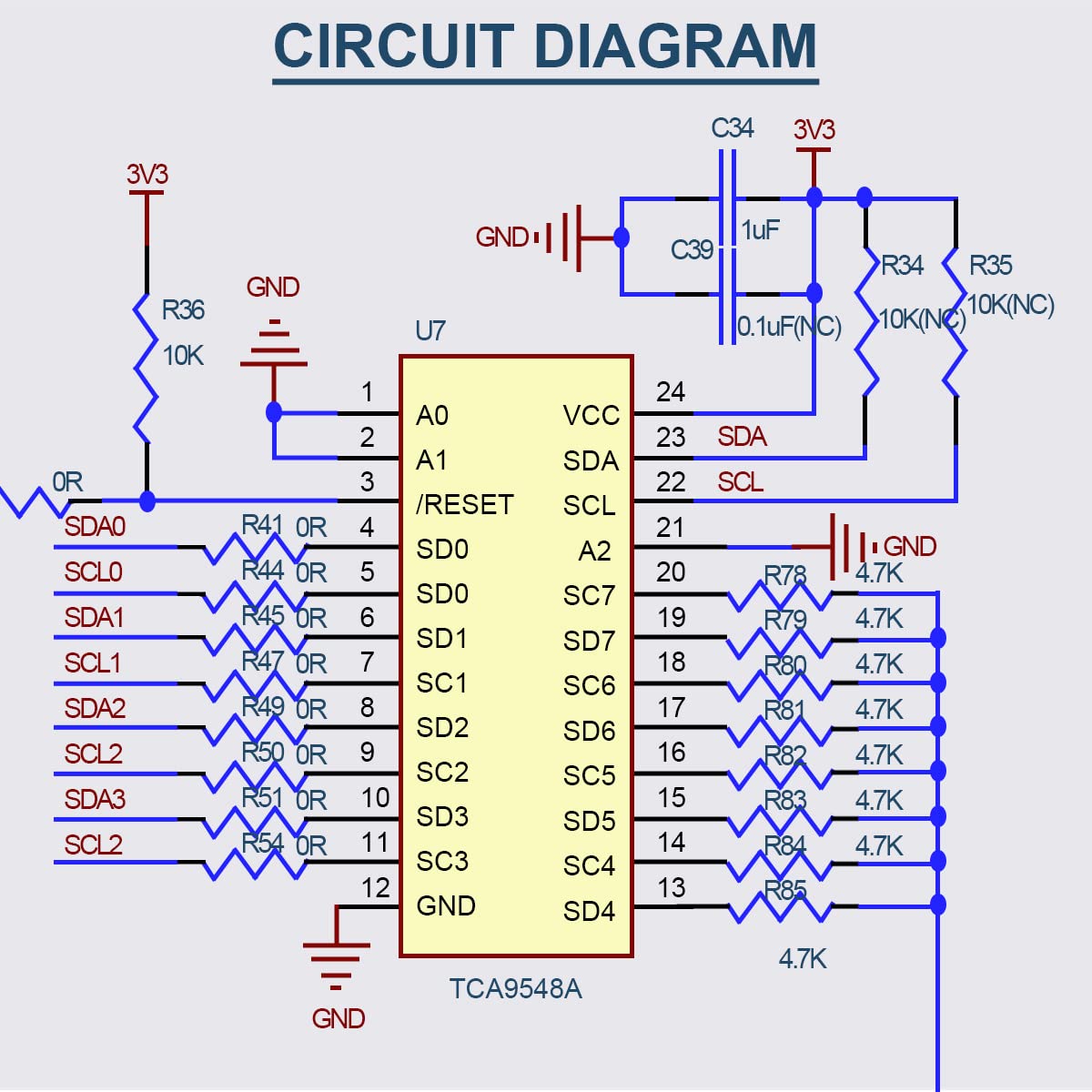
Figure 5: Circuit Diagram of the TCA9548A I2C Multiplexer Breakout Board.
4.1 Pin Descriptions
- VIN: Input voltage for the board.
- GND: Ground connection.
- SDA: Main I2C Data line.
- SCL: Main I2C Clock line.
- RST: Reset pin (active-low).
- A0, A1, A2: Address selection pins for configuring the multiplexer's own I2C address.
- SC0-SC7 (SDA/SCL pairs): Eight multiplexed I2C channels for connecting peripheral devices.
5. Setup and Connection
To set up the TCA9548A IIC Multiplexer, follow these general steps:
- Power Connection: Connect the VIN pin to your power supply (1.65V to 5.5V) and GND to the system ground.
- Main I2C Bus Connection: Connect the SDA and SCL pins of the multiplexer to the I2C bus of your microcontroller (I2C Master).
- Peripheral Device Connection: Connect your I2C peripheral devices to the desired multiplexed channels (SC0-SC7). Each channel consists of an SDA and SCL line.
- Address Configuration: The default I2C address of the TCA9548A is 0x70. If you are using multiple TCA9548A boards or need a different address, configure the A0, A1, and A2 pins accordingly. These pins allow for up to 8 unique addresses (0x70 to 0x77).
- Reset Pin: The RST pin is active-low. Connect it to your microcontroller if you need to programmatically reset the multiplexer, or pull it high if not used.
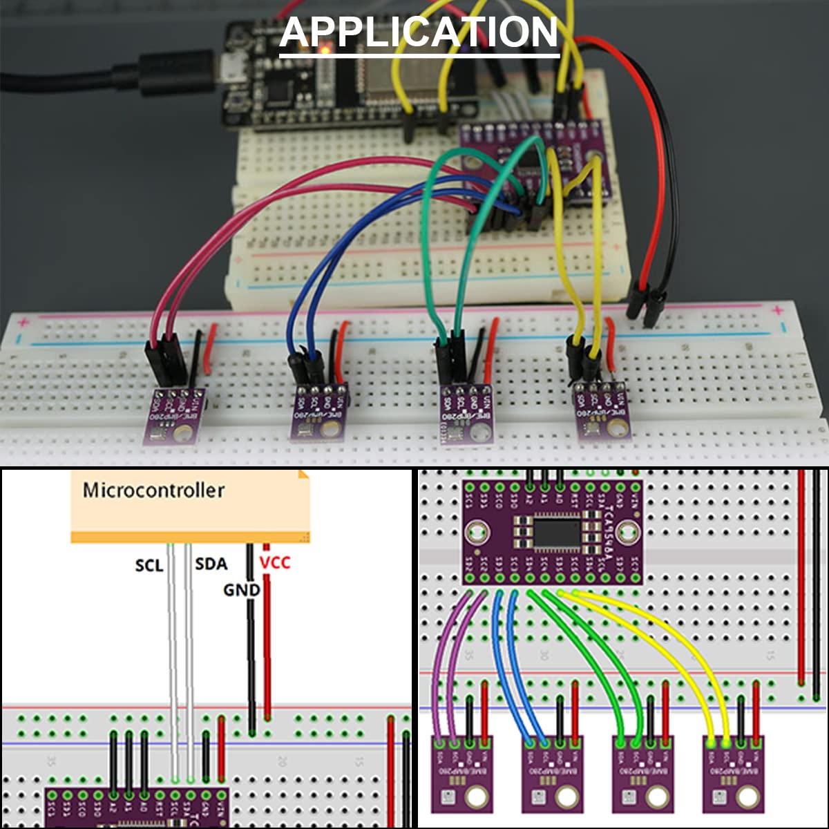
Figure 6: Example application setup for the TCA9548A I2C Multiplexer.
6. Operation
Operating the TCA9548A involves selecting the desired I2C channel before communicating with a peripheral device connected to that channel.
- Initialize I2C: Ensure your microcontroller's I2C communication is properly initialized.
- Select Channel: To communicate with a device on a specific channel (e.g., SC0), send a single byte to the TCA9548A's I2C address (default 0x70). The byte should contain a bitmask where the bit corresponding to the desired channel is set to '1'. For example, to select channel 0, send
0b00000001(0x01). To select channel 1, send0b00000010(0x02), and so on. - Communicate with Device: After selecting the channel, all subsequent I2C communications from the microcontroller will be routed through the selected channel to the connected peripheral device.
- Deselect Channel (Optional): To deselect a channel or switch to another, send a new byte with the appropriate bitmask. Sending
0b00000000(0x00) will deselect all channels.
Refer to the TCA9548A datasheet for detailed register information and advanced control options.
Video 1: Demonstration of the CJMCU-9548 TCA9548A 1-to-8 I2C 8-Way Multi-Channel Multiplexer in operation.
7. Maintenance
- Storage: Store the breakout board in an anti-static bag in a dry environment to prevent damage from static discharge and moisture.
- Cleaning: If necessary, gently clean the board with a soft, dry brush or compressed air. Avoid using liquids or abrasive materials.
- Inspection: Periodically inspect the solder joints and connections for any signs of damage or corrosion.
- Handling: Always handle the board by its edges to avoid touching the electronic components, which can cause static damage or introduce contaminants.
8. Troubleshooting
- Device Not Detected:
- Verify all power and ground connections are secure.
- Check the main I2C SDA/SCL lines from the microcontroller to the multiplexer.
- Ensure the correct I2C address for the TCA9548A is being used (default 0x70).
- Confirm the correct channel is selected on the multiplexer before attempting to communicate with the peripheral device.
- Check the connections from the selected multiplexer channel (SCx SDA/SCL) to the peripheral device.
- Ensure the peripheral device itself is powered and functioning correctly.
- Check for proper pull-up resistors on both the main I2C bus and the multiplexed I2C channels, if required by your setup.
- Intermittent Communication:
- Inspect for loose connections or cold solder joints.
- Ensure proper power supply stability.
- Check for excessive cable length or noise on the I2C lines.
- Incorrect I2C Address:
- The default address is 0x70. If using A0, A1, A2 pins, ensure they are set correctly to achieve the desired address (0x70-0x77).
- Use an I2C scanner sketch with your microcontroller to detect the actual address of the multiplexer.
9. Package Contents
Each package includes:
- 5 x TCA9548A I2C IIC Multiplexer Breakout Board
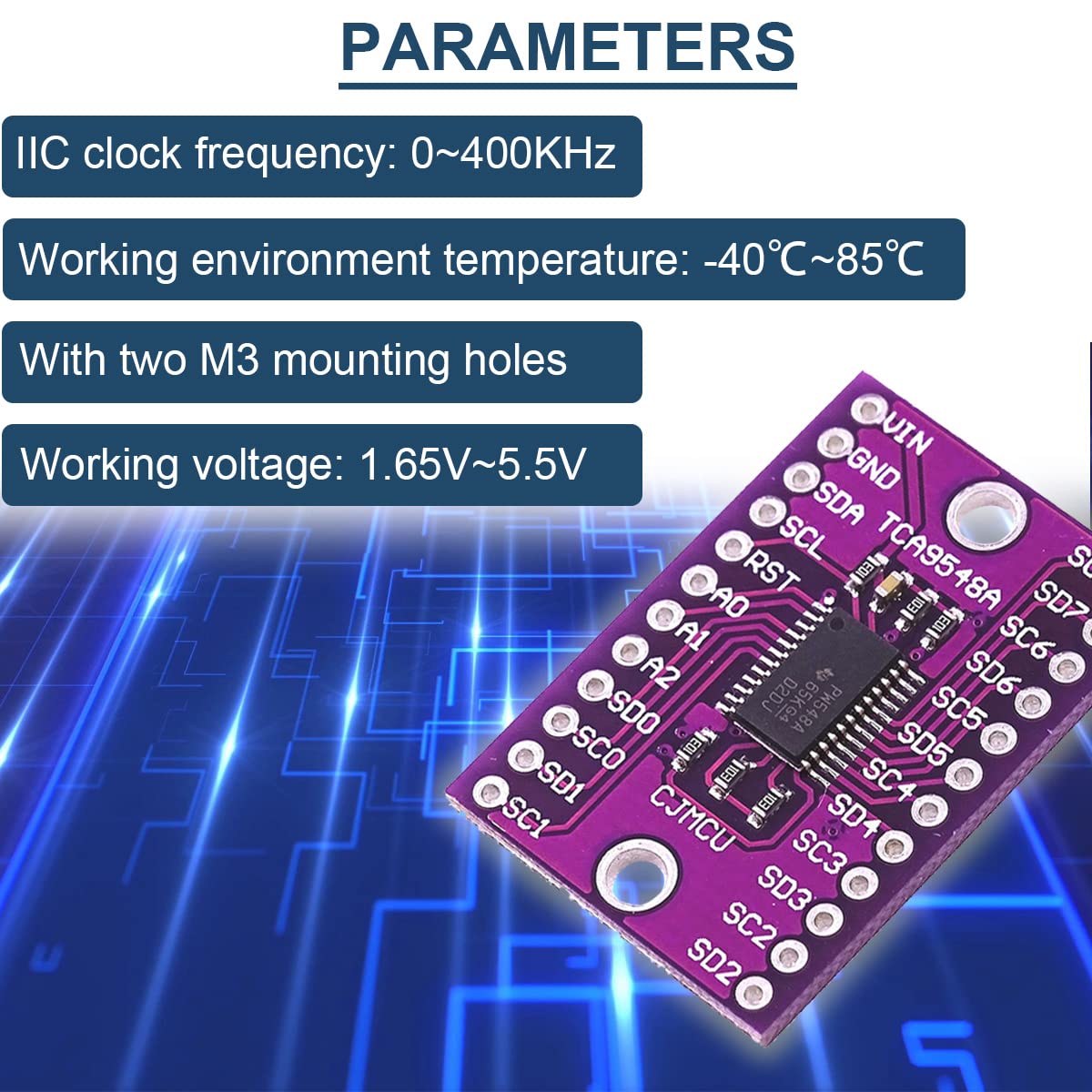
Figure 7: Contents of the TCA9548A I2C IIC Multiplexer Breakout Board package.
10. Support
For technical assistance, troubleshooting, or further inquiries, please refer to the official DAOKAI support channels or product documentation. Ensure you have your product model number (WE-DA-068) available when seeking support.


