1. Product Overview
The EPEVER Tracer5210BP is a 20A MPPT solar charge controller designed for 12V/24V battery systems. It features IP67 waterproofing, high tracking efficiency, and supports various battery types including lead-acid (sealed, gel, flooded) and lithium (LiFePO4, Li-NiCoMn), as well as user-defined settings. This kit includes the Tracer5210BP controller, an MT50 remote meter, and an RS485 communication cable for comprehensive system monitoring and control.

Figure 1: EPEVER Tracer5210BP MPPT Solar Charge Controller Kit, including the controller, MT50 remote meter, RS485 cable, and mounting hardware.
The controller is engineered for durability with a gel-potted design for improved heat dissipation and an IP67 waterproof rating, making it suitable for various outdoor and demanding environments such as solar RVs, camping setups, household systems, industrial monitoring, traffic signals, and marine applications.

Figure 2: The Tracer5210BP controller demonstrating its IP67 waterproof capability, submerged in water.
2. Safety Instructions and Protections
Adhere to the following safety guidelines during installation and operation:
- Ensure all wiring is correctly polarized and securely connected to prevent damage to the controller or connected devices.
- Always connect the battery first, then the solar panel, and finally the load. Disconnect in the reverse order.
- Do not attempt to disassemble or repair the controller unless you are a qualified technician.
- Install the controller in a well-ventilated area, even with its gel-potted design, to ensure optimal performance and longevity.
- Verify battery voltage and type settings match your battery bank to prevent overcharging or undercharging.
2.1 Electronic Protections
The Tracer5210BP controller incorporates multiple electronic protections to ensure safe and reliable operation:
- PV Over Current
- PV Short Circuit
- PV Reverse Polarity
- Battery Reverse Polarity
- Battery Over Voltage
- Battery Over Discharge
- Battery Overheating
- Lithium battery Low Temperature
- Load Overload
- Load Short Circuit
- Temperature sensor break down

Figure 3: List of electronic protections integrated into the Tracer BP series controllers.
3. Setup and Installation
3.1 Package Contents
- 1 x EPEVER Tracer5210BP MPPT Solar Charge Controller (20A)
- 1 x Remote Meter (MT50)
- 1 x Communication Cable (CC-RS485-RS485-150U-4LLT)
- Mounting hardware (screws, anchors)
- User Manuals (for controller and MT50)
3.2 Mounting the Controller
The Tracer5210BP controller should be mounted vertically on a flat surface to allow for proper heat dissipation. Ensure there is adequate space around the controller for air circulation and cable connections. The mounting hole size is 3.5mm, and the mounting dimension is 120x94mm.

Figure 4: Dimensions of the EPEVER Tracer5210BP controller, showing its length, width, and height for mounting reference.
3.3 Wiring Connections
Follow the connection diagram carefully. The recommended wire size for the 20A model is 12AWG (4mm²). Ensure all connections are tight and secure.
- Connect the Battery: Connect the battery to the controller first. Ensure correct polarity (positive to positive, negative to negative).
- Connect the Solar Panel: Connect the solar panel array to the controller. Ensure correct polarity.
- Connect the DC Load (Optional): Connect the DC load to the controller.
Disconnection Sequence: When disconnecting the system, follow the reverse order: disconnect the load, then the solar panel, and finally the battery.
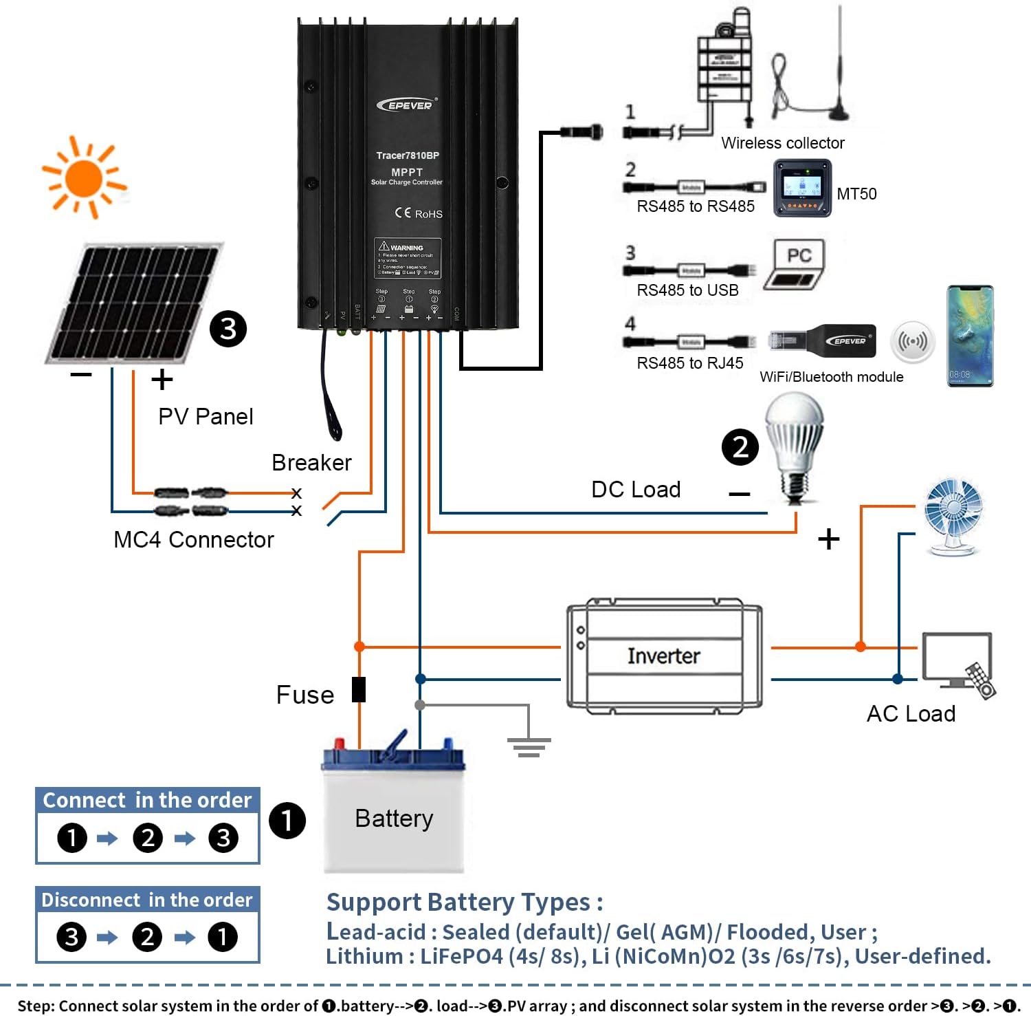
Figure 5: Detailed connection diagram illustrating the proper wiring sequence for the solar panel, battery, and DC load to the Tracer5210BP controller, along with optional accessories like an inverter and communication modules.
3.4 Battery Type Selection
The controller supports various battery types. The default setting is Sealed lead-acid. For lithium batteries, the system voltage must be manually selected. Use the MT50 remote meter or the APP/PC software to configure the battery type and parameters.
- Lead-acid Batteries: Sealed (Default), Gel (AGM), Flooded
- Lithium Batteries: LiFePO4, Li-NiCoMn
- User-defined: Allows custom parameter settings.
4. Operating Instructions
4.1 LED Indicators
The controller features LED indicators to display its operational status and any potential issues. Refer to the table below for detailed explanations.
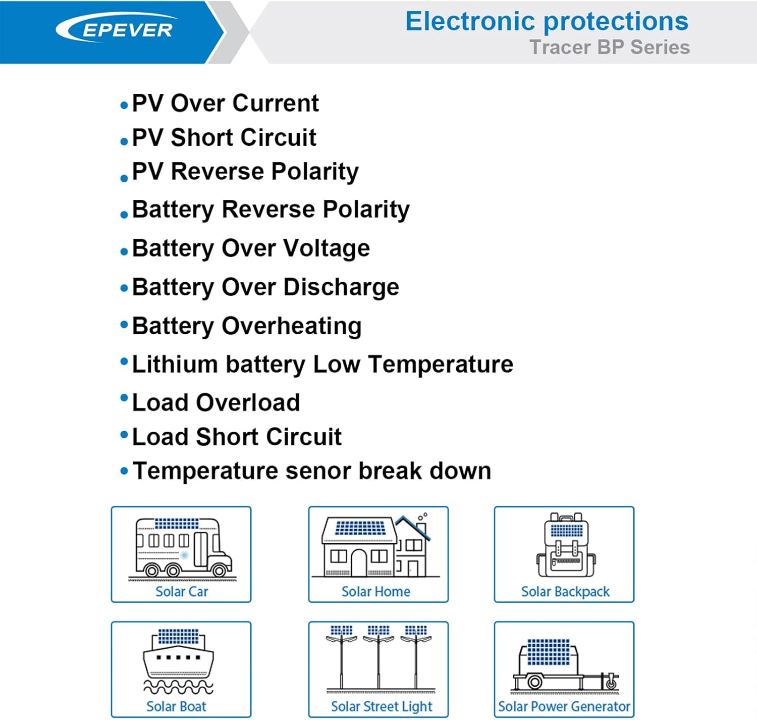
Figure 6: Table detailing the meaning of the PV and BATT LED indicators based on their color and status (On Solid, OFF, Slowly Flashing, Fast Flashing).
Note: When the battery type is Lithium Battery, the controller does not automatically recognize the system voltage.
4.2 Load Working Modes
The controller supports multiple load control working modes:
- Manual Mode: Load is controlled manually.
- Light ON/OFF (Default): Load turns on at dusk and off at dawn.
- Light ON + Timer: Load turns on at dusk and stays on for a set duration.
- Real-time Control Mode: Allows setting load ON/OFF times via a real-time clock.
Note: In Light ON/OFF and Light ON + Timer modes, the load is turned on after a 10-minute delay.

Figure 7: Diagrams illustrating the different load working modes: Manual, Light ON/OFF, Light ON + Timer, and Real-time Control.
4.3 MT50 Remote Meter
The MT50 remote meter provides real-time display of system status and data, and allows for convenient parameter adjustment. Connect the MT50 to the controller using the provided RS485 communication cable.

Figure 8: The EPEVER MT50 Remote Meter, used for monitoring and configuring the solar charge controller.
The MT50 allows you to:
- View charging and discharging parameters.
- Monitor real-time energy statistics.
- Set battery type and charging parameters.
- Configure load working modes.
5. Maintenance
The EPEVER Tracer5210BP is designed for low maintenance due to its IP67 rating and robust construction. However, regular checks are recommended to ensure optimal performance and longevity of your solar system.
- Inspect Connections: Periodically check all wiring connections for tightness and corrosion. Loose connections can cause voltage drops and overheating.
- Clean the Controller: Although waterproof, ensure the controller's exterior is free from excessive dust or debris that could hinder heat dissipation. Use a soft, dry cloth for cleaning.
- Battery Inspection: For lead-acid batteries, check electrolyte levels (if applicable) and terminal cleanliness. For all battery types, monitor battery voltage and health via the MT50 or monitoring software.
- Solar Panel Cleaning: Keep solar panels clean to maximize energy harvest.
6. Troubleshooting
This section provides guidance for common issues. For more complex problems, contact technical support.
| Fault | Possible Reasons | Troubleshooting |
|---|---|---|
| LED Charging indicator OFF during daytime when sunshine falls on PV modules properly | PV array disconnection | Confirm that PV and battery wire connections are correct and tight. |
| No LED indicator | Battery voltage maybe less than 8.5V | Measure battery voltage with a multi-meter. Minimum 8.5V is required to start the controller. |
| Battery LED indicator green fast flashing | Battery over voltage | Check if battery voltage is higher than OVD (Over Voltage Disconnect) and disconnect the PV. |
| Battery LED indicator red | Battery over discharged | When the battery voltage is restored to or above LVR point (Low Voltage Reconnect voltage), the load will recover. |
| Battery LED indicator red flashing | Battery Overheating | The controller will automatically turn the system off. When the temperature declines to below 50°C, the controller will resume. |
| Load is not output | Load Overload | 1. Reduce the number of electric equipment. 2. Restart the controller. 3. Wait for one night-day cycle (night time > 3 hours). |
| Load is not output | Load Short Circuit | 1. Check carefully load connections, clear the fault. 2. Restart the controller. 3. Wait for one night-day cycle (night time > 3 hours). |
Note: When there is an overload or short circuit, the load has 5 times auto-recovery function, each time delay respectively 5s, 10s, 15s, 20s, 25s.
7. Technical Specifications
Below are the detailed technical specifications for the Tracer5210BP model.

Figure 9: Detailed technical specifications for the Tracer BP series, including the Tracer5210BP model.
| Item/Model | Tracer5210BP |
|---|---|
| Nominal system voltage | 12V/24VDC Auto (Lithium battery do not automatic identification system voltage) |
| Battery input voltage range | 8.5~32VDC |
| Rated charge/discharge current | 20 Amp |
| Max. PV input power | 260W (12V system) / 520W (24V system) |
| Max. PV open circuit voltage | 100V (at minimum operating environment temperature); 92V (at 25℃ environment temperature) |
| MPP voltage range | V(BAT+2V)~72V |
| Battery Type | Lead-acid: Sealed (Default), Gel, Flooded; Lithium battery: LiFePO4, Li-NiCoMn; User |
| Equalize Charging Voltage (Lead-acid) | Sealed: 14.6V/Gel: No/Flooded: 14.8V (User: 9-17V (X2/24V)) |
| Boost Charging Voltage (Lead-acid) | Sealed: 14.4V/Gel: 14.2V/Flooded: 14.6V (User: 9-17V (X2/24V)) |
| Float Charging Voltage (Lead-acid) | Sealed/Gel/Flooded: 13.8V (User: 9-17V (X2/24V)) |
| Low Voltage Reconnect Voltage (Lead-acid) | Sealed/Gel/Flooded: 12.6V (User: 9-17V (X2/24V)) |
| Low Voltage Disconnect Voltage (Lead-acid) | Sealed/Gel/Flooded: 11.1V (User: 9-17V (X2/24V)) |
| Boost Charging Voltage (Lithium) | LiFePO4: 14.5V/Li-NiCoMn: 12.5V (User: 9-17V (X2/24V)) |
| Low Voltage Reconnect Voltage (Lithium) | LiFePO4: 12.8V/Li-NiCoMn: 10.5V (User: 9-17V (X2/24V)) |
| Low Voltage Disconnect Voltage (Lithium) | LiFePO4: 11.1V/Li-NiCoMn: 9.3V (User: 9-17V (X2/24V)) |
| Self-consumption | ≤13mA (12V); ≤11.5mA (24V) |
| Temperature compensation coefficient | -3mV/℃/2V (Lithium battery don’t have temperature compensation coefficient) |
| Communication | RS485 |
| Working environment temperature | -40℃~+60℃ |
| Enclosure | IP67 |
| Overall dimension | 153.3 x 105 x 52.1 mm |
| Mounting hole size | 3.5 mm |
| Mounting dimension | 120 x 94 mm |
| Power cable | 12AWG (4mm²) |
| Net weight | 1.20 KG |
8. Support
For technical assistance or further inquiries, please contact EPEVER's authorized service centers. GolandCentury, an authorized sales agent for EPEVER, provides free technical support through their service centers located in Chicago (USA), Munich (Germany), Toronto (Canada), and Melbourne (Australia).
For the latest information and software updates, please visit the official EPEVER website or contact your local distributor.


