
1. Introduction
The ZOTEK ZT-QS9 is a True-RMS digital clamp meter designed for accurate measurement of various electrical parameters. It is suitable for both commercial and household electrical troubleshooting, offering a wide range of functions including AC/DC Current, AC/DC Voltage, Frequency, Duty Cycle, Resistance, Capacitance, Diode, Continuity, and Temperature tests. Key features include Inrush Current measurement, Peak Hold, LowZ, NCV, flashlight, and auto power-off.
2. Safety Information
Always observe basic safety precautions when using this device to avoid electric shock, injury, or damage to the meter or equipment under test. Read and understand all instructions before use.
- Do not exceed the maximum input values for any function.
- Use caution when working with voltages above 30V AC RMS, 42V peak, or 60V DC. These voltages pose a shock hazard.
- Ensure the test leads are properly connected and the function switch is set to the correct range before making measurements.
- Inspect test leads for damaged insulation or exposed metal. Replace if damaged.
- Do not operate the meter if it appears damaged or if the case is open.
- Remove test leads from the circuit before changing functions.
- When measuring current, clamp the meter around a single conductor, not the entire power cord.
3. Package Contents
Verify that all items are present in the package:
- ZOTEK ZT-QS9 Digital Clamp Meter
- Test Leads (Red and Black)
- Carrying Pouch
- Thermocouple (for temperature measurement)
- AAA Batteries (2x)
- User Manual (this document)

4. Product Overview
The ZT-QS9 features a compact design with a clear LCD display and intuitive controls.

4.1 Key Components:
- Pliers Head: For non-contact current measurement. Maximum jaw opening is 22mm.
- LED Flashlight: Illuminates dimly lit work areas.
- Trigger: Opens the clamp jaws.
- Function Selection Switch: Rotary dial to select measurement modes.
- Buttons: SEL (Select), NCV, INRUSH/PEAK, REL (Relative), MIN/MAX, HOLD.
- LCD Monitor: Digital display for measurement readings.
- Measurement Input Terminals: For connecting test leads for voltage, resistance, diode, continuity, and capacitance measurements.

5. Setup
5.1 Battery Installation
The ZT-QS9 is powered by 2 AAA batteries. To install or replace batteries:
- Ensure the meter is turned off and all test leads are disconnected.
- Locate the battery compartment cover on the back of the meter.
- Unscrew the retaining screw(s) and remove the cover.
- Insert two AAA batteries, observing correct polarity (+/-).
- Replace the battery compartment cover and secure the screw(s).
A low battery indicator will appear on the display when batteries need replacement.
6. Operating Instructions
Turn the function selection switch to the desired measurement mode. Connect test leads to the appropriate input jacks for voltage, resistance, diode, continuity, or capacitance measurements. For current measurements, use the clamp jaws.
6.1 AC/DC Voltage Measurement
To measure AC or DC voltage:
- Set the function switch to the V~ (AC Voltage) or V= (DC Voltage) position.
- Insert the red test lead into the VΩHz jack and the black test lead into the COM jack.
- Connect the test probes across the circuit or component to be measured.
- Read the voltage value on the LCD display.
Refer to Video 6.1 for a demonstration of DC Voltage measurement (0:00-0:01) and AC Voltage measurement (0:01-0:02).
6.2 AC/DC Current Measurement (Clamp)
To measure AC or DC current using the clamp jaws:
- Set the function switch to the A~ (AC Current) or A= (DC Current) position.
- Press the trigger to open the clamp jaws.
- Enclose a single conductor (not the entire power cord) within the clamp jaws.
- Ensure the conductor is centered within the jaws for accurate readings.
- Read the current value on the LCD display.
- For DC current, press and hold the "REL" key for two seconds to clear the reading before measurement.

6.3 Resistance Measurement
To measure resistance:
- Set the function switch to the Ω (Resistance) position.
- Insert the red test lead into the VΩHz jack and the black test lead into the COM jack.
- Ensure the circuit or component is de-energized before connecting the test probes.
- Connect the test probes across the component.
- Read the resistance value on the LCD display.
Refer to Video 6.1 for a demonstration of Resistance measurement (0:02-0:03).
6.4 Diode Test
To perform a diode test:
- Set the function switch to the Diode position (often shared with continuity or resistance, use the SEL button to cycle).
- Insert the red test lead into the VΩHz jack and the black test lead into the COM jack.
- Connect the red probe to the anode and the black probe to the cathode of the diode.
- A forward voltage drop will be displayed. Reverse the probes; an "OL" (Open Line) reading indicates a good diode.
Refer to Video 6.1 for a demonstration of Diode measurement (0:03-0:04).
6.5 Continuity Test
To perform a continuity test:
- Set the function switch to the Continuity position (often shared with diode or resistance, use the SEL button to cycle).
- Insert the red test lead into the VΩHz jack and the black test lead into the COM jack.
- Connect the test probes across the circuit or component.
- If continuity exists (resistance below a certain threshold), the meter will emit an audible beep.
Refer to Video 6.1 for a demonstration of Continuity Test (0:04-0:05).
6.6 Capacitance Measurement
To measure capacitance:
- Set the function switch to the Capacitance position (often shared with other functions, use the SEL button to cycle).
- Insert the red test lead into the VΩHz jack and the black test lead into the COM jack.
- Ensure the capacitor is fully discharged before connecting the test probes.
- Connect the test probes across the capacitor.
- Read the capacitance value on the LCD display.
Refer to Video 6.1 for a demonstration of Capacitance measurement (0:05-0:06).
6.7 Temperature Measurement
To measure temperature:
- Set the function switch to the °C/°F (Temperature) position.
- Connect the thermocouple to the input jacks, observing polarity.
- Place the thermocouple probe at the point where temperature needs to be measured.
- Read the temperature value on the LCD display. Use the SEL button to switch between Celsius and Fahrenheit.
Refer to Video 6.1 for a demonstration of Temperature measurement (0:06-0:07).
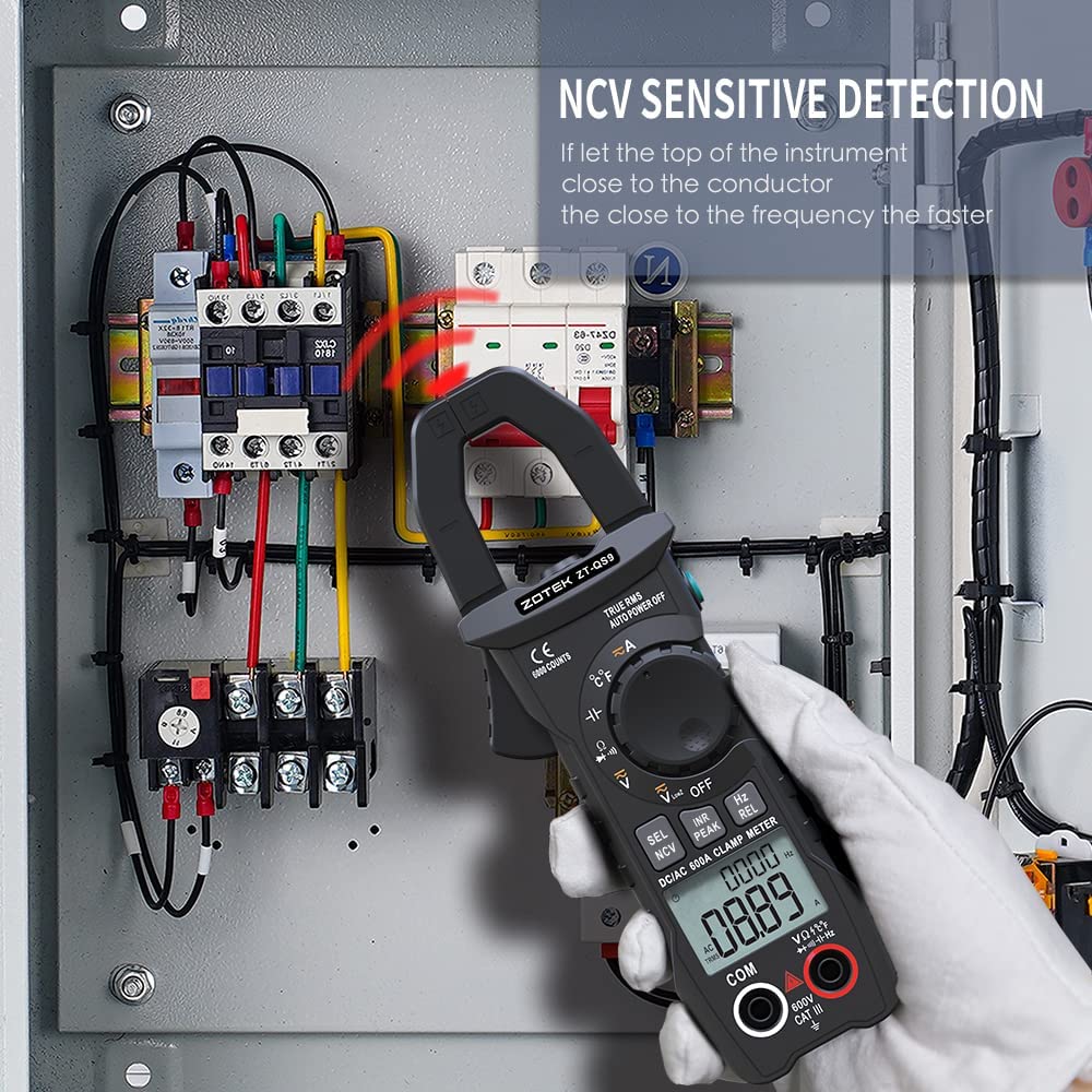
6.8 Non-Contact Voltage (NCV) Detection
To detect AC voltage without contact:
- Set the function switch to the NCV position.
- Bring the top of the meter close to the conductor or outlet.
- The meter will emit an audible beep and the NCV indicator will light up, with the frequency of beeps increasing as it gets closer to a live voltage source.
6.9 Neutral Line and Live Line Judgment
To distinguish between neutral and live lines:
- Set the function switch to the NCV position.
- Insert the red test lead into the VΩHz jack.
- Touch the red probe to the suspected live wire. If it's a live wire, the meter will display "EF" and emit a rapid beep. If it's a neutral wire, there will be no indication or a very weak one.
Refer to Video 6.1 for a demonstration of Neutral Line and Live Line Judgment (0:07-0:08).
6.10 Inrush Current Measurement
To measure the instantaneous starting current of equipment:
- Set the function switch to the A~ (AC Current) or A= (DC Current) position.
- Press the INRUSH/PEAK button.
- Clamp the meter around a single conductor of the device you wish to measure as it starts up.
- The meter will capture and display the peak inrush current. Note: The inrush function detects current of 5 amps or more.
6.11 Other Functions
- True-RMS: Provides accurate measurements on non-linear loads.
- Peak Hold: Automatically saves peak voltage when measuring circuit voltage.
- LowZ: Low input impedance helps prevent false readings due to ghost voltage.
- Flashlight: Press the flashlight button to illuminate the work area.
- Auto Power Off: The meter automatically shuts down after 15 minutes of inactivity to conserve battery life.
- Data Hold: Press the HOLD button to freeze the current reading on the display.
7. Specifications
Technical specifications for the ZOTEK ZT-QS9 Digital Clamp Meter:
| Function | Range | Resolution | Accuracy | MAX. Value | Frequency Response |
|---|---|---|---|---|---|
| DC Voltage | 6.000V | 0.001V | ±(0.5%+3) | 600V | |
| 60.00V | 0.01V | ||||
| 600.0V | 0.1V | ||||
| AC Voltage (V) | 6.000V | 0.001V | ±(1%+3) | 600V | 40Hz-1kHz |
| 60.00V | 0.01V | ||||
| 600.0V | 0.1V | ||||
| DC Current | 60.00A | 0.01A | ±(2.0%+30) | 600A | |
| 600.0A | 0.1A | ||||
| AD Current | 60.00A | 0.01A | ±(2.0%+30) | 600A | 40Hz-400Hz |
| 600.0A | 0.1A | ||||
| Resistance | 600.0Ω | 0.1Ω | ±(1.5%+3) | 60MΩ | |
| 6.000kΩ | 0.001kΩ | ||||
| 60.00kΩ | 0.01kΩ | ||||
| 600.0kΩ | 0.1kΩ | ||||
| 6.000MΩ | 0.001MΩ | ||||
| 60.00MΩ | 0.01MΩ | ±(5.0%+20) | |||
| Capacitance | 6.000nF | 0.001nF | ±(5.0%+5) | 60.00mF | |
| 60.00nF | 0.01nF | ||||
| 600.0nF | 0.1nF | ||||
| 6.000µF | 0.001µF | ±(2.0%+5) | |||
| 60.00µF | 0.01µF | ||||
| 600.0µF | 0.1µF | ||||
| 6.000mF | 0.001mF | ||||
| 60.00mF | 0.01mF | ±(5.0%+5) | |||
| Frequency | 60.00Hz | 0.01Hz | ±(0.1%+2) | 300.0kHz | |
| 600.0Hz | 0.1Hz | ||||
| 6.000kHz | 0.001kHz | ||||
| 60.00kHz | 0.01kHz | ||||
| 300.0kHz | 0.1kHz | ||||
| Diode | √ | ||||
| Continuity | √ | ||||
| Inrush current | √ | ||||
| Flashlight | √ | ||||
| Temperature | -30~1000°C | 1°C | ±(2.5%+5) | 1832°F | |
| -22~1832°F | 1°F |
General Specifications:
- Display: LCD, 6000 counts
- Ranging: Auto
- Material: ABS
- Update Rate: 3 times/second
- True RMS: Yes
- Data Hold: Yes
- Low Battery Alert: Yes
- Auto Power Off: Yes
Mechanical Specifications:
- Dimension: 185 x 65 x 30mm
- Weight: 165g
- Battery Type: 1.5V AAA Battery * 2
Environmental Specifications:
- Operating Temperature: 0°C to 40°C
- Operating Humidity: < 75%
- Storage Temperature: -20°C to 60°C
- Storage Humidity: < 80%

8. Maintenance
8.1 Cleaning
Wipe the meter's case with a damp cloth and mild detergent. Do not use abrasives or solvents. Ensure the meter is dry before storage or use.
8.2 Battery Replacement
Replace batteries when the low battery indicator appears on the display. Refer to Section 5.1 for battery installation instructions.
8.3 Storage
If the meter is not used for an extended period, remove the batteries to prevent leakage and damage. Store the meter in a cool, dry place away from direct sunlight and extreme temperatures.
9. Troubleshooting
This section provides solutions to common issues encountered with the ZT-QS9 clamp meter.
- Meter does not power on: Check battery installation and ensure batteries are not depleted. Replace if necessary.
- No reading or "OL" displayed (except for diode reverse bias): Ensure test leads are properly connected to the correct jacks and making good contact with the circuit. Verify the function switch is in the correct position for the measurement type. For current, ensure only one conductor is within the clamp jaws.
- Inaccurate readings: Check battery level. Ensure test leads are not damaged. For current measurements, ensure the conductor is centered in the clamp. Avoid strong electromagnetic fields.
- Continuity test does not beep: Ensure the circuit is de-energized. Check for actual continuity in the circuit.
10. Warranty and Support
The ZOTEK ZT-QS9 Digital Clamp Meter comes with a one-year warranty from the manufacturer (ZOYI). For warranty claims, technical support, or service inquiries, please contact your retailer or the manufacturer directly. Keep your purchase receipt as proof of purchase.
Manufacturer: ZOYI
Date First Available: April 18, 2022
