
QCCAN QCCAN-USB-BoostBuck-2PCS
USB Step UP/Down Power Supply Module Instruction Manual
Brand: QCCAN | Model: QCCAN-USB-BoostBuck-2PCS
1. Introduction
The QCCAN USB Step UP/Down Power Supply Module is a versatile DC-DC boost/buck converter designed to provide adjustable output voltage from a standard USB 5V input. This module features an integrated voltage display, allowing for precise monitoring of the output. It supports both standard USB and Micro USB inputs, making it highly adaptable for various electronic projects and applications.
Each package includes two such modules, offering flexibility for multiple uses such as powering different devices, charging batteries, or serving as an instrument voltage display.

Figure 1: Two QCCAN USB Step UP/Down Power Supply Modules.
2. Product Features
- USB Powered: Can be powered directly via standard USB-A or Micro USB 5V input.
- Adjustable Output: Output voltage is adjustable from 1.2V to 24V DC.
- Integrated Display: Features a digital voltage display for real-time output monitoring.
- Boost/Buck Capability: Functions as both a step-up (boost) and step-down (buck) converter.
- Control Buttons: Includes an ON/OFF button for the output and a separate function for the display.
- Data Storage: Remembers the last set output state even after power-off.
- Multiple Input Options: Supports standard USB, Micro USB, and solder pads for input voltage (3.5V-12V).
3. Setup and Connections
Before connecting the module, ensure your power source meets the input requirements and that your load does not exceed the module's capabilities. Refer to the labeled diagram below for component identification.
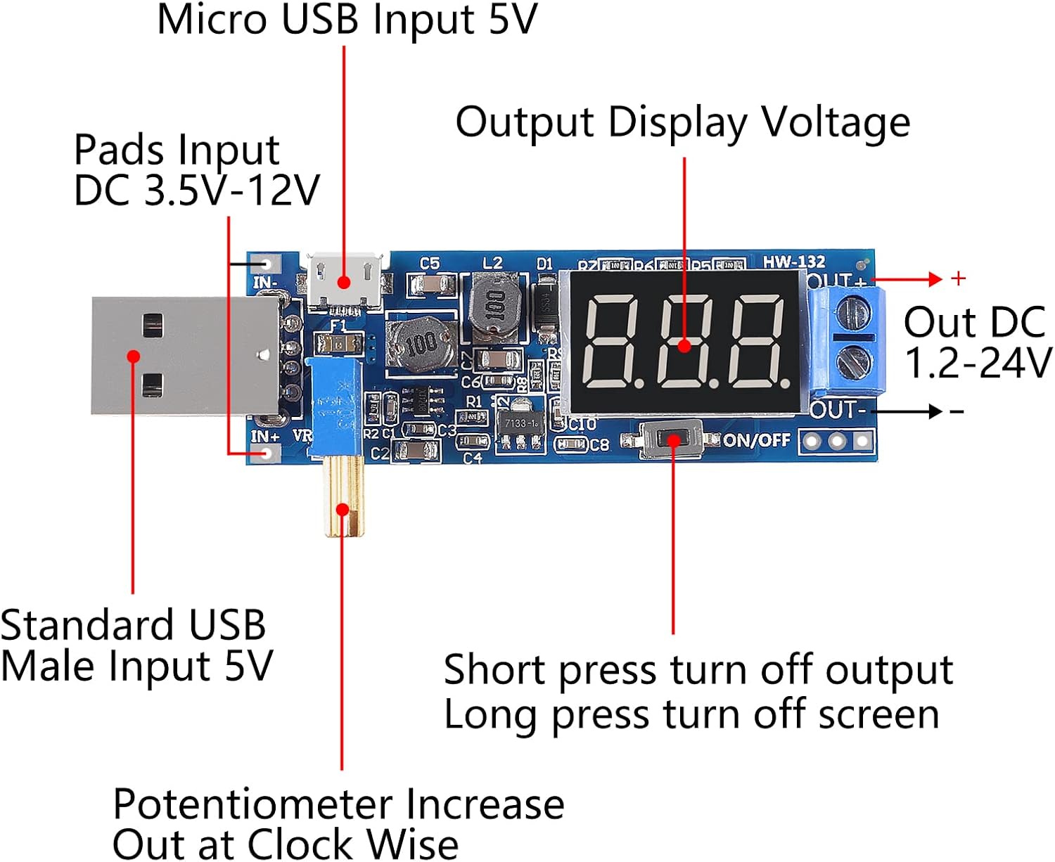
Figure 2: Component Layout and Connection Points.
- Input Power: Connect a 5V USB power source to either the Standard USB Male Input or the Micro USB Input. Alternatively, for input voltages between 3.5V and 12V, use the Pads Input (VIN and GND).
- Output Connection: Connect your load to the "OUT+" and "OUT-" screw terminals. Ensure correct polarity.
- Potentiometer: The blue potentiometer with a brass screw allows for adjustment of the output voltage.
- ON/OFF Button: A short press of this button will turn the output ON or OFF. A long press will turn the digital display screen ON or OFF, while the output remains active.
It is recommended to adjust the output voltage to your desired level before connecting your sensitive electronic devices to prevent damage.
4. Operating Instructions
Once the module is powered on, the digital display will show the current output voltage. Follow these steps to operate the module:
- Adjusting Output Voltage: Rotate the potentiometer clockwise to increase the output voltage and counter-clockwise to decrease it. The display will update in real-time.
- Turning Output ON/OFF: Briefly press the "ON/OFF" button to toggle the power output to the terminals. When the output is off, the display may show "OFF" or a low voltage.
- Display Control: Press and hold the "ON/OFF" button for approximately 3 seconds to turn the digital voltage display ON or OFF. This can be useful for power saving or in applications where the display is not needed. The output will remain active regardless of the display state.
- Data Storage: The module automatically saves the last set output voltage and ON/OFF state. This means it will resume its previous configuration when powered on again.
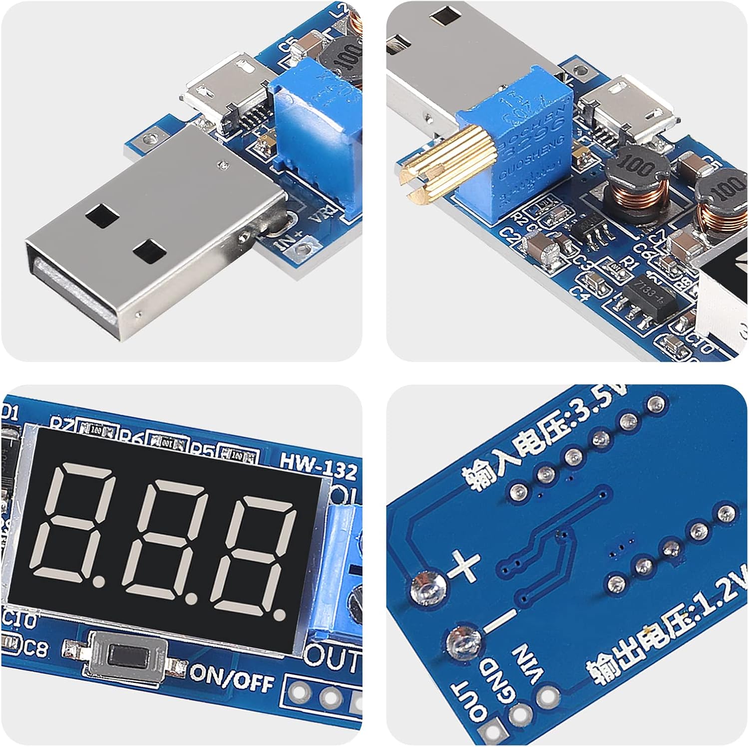
Figure 3: Detail of the Potentiometer and Display.
5. Maintenance
To ensure the longevity and optimal performance of your USB Step UP/Down Power Supply Module, consider the following maintenance guidelines:
- Cleanliness: Keep the module free from dust, dirt, and moisture. Use a soft, dry cloth for cleaning. Avoid using liquid cleaners.
- Environmental Conditions: Operate the module within its specified temperature and humidity ranges. Avoid extreme heat, cold, or high humidity.
- Physical Handling: Handle the module with care to avoid damaging the electronic components or the potentiometer.
- Ventilation: Ensure adequate airflow around the module, especially during prolonged operation or when drawing higher currents, to prevent overheating.
6. Troubleshooting
If you encounter issues with your power supply module, refer to the following common problems and solutions:
| Problem | Possible Cause / Solution |
|---|---|
| Module does not power on or display is blank. |
|
| Output voltage is unstable or incorrect. |
|
| Module gets excessively hot. |
|
| Output does not turn on for high startup current devices (e.g., motors). |
|
7. Specifications
| Feature | Detail |
|---|---|
| Input Voltage | 5V (via USB-A or Micro USB), 3.5V-12V (via pads) |
| Output Voltage | 1.2V - 24V DC (Adjustable) |
| Module Type | Boost/Buck Converter (Step UP/Down) |
| Display | Digital Voltage Display |
| Dimensions | Approx. 64mm x 22mm (2.51 x 0.86 inches) |
| Item Weight | 1.13 ounces (per module) |
| Model Number | QCCAN-USB-BoostBuck-2PCS |

Figure 4: Module Dimensions.
8. Warranty and Support
For any questions, technical assistance, or warranty inquiries regarding your QCCAN USB Step UP/Down Power Supply Module, please contact the seller or manufacturer directly through the platform where the purchase was made. Please retain your proof of purchase for any warranty claims.
Ask a question about this manual
Ask about setup, troubleshooting, compatibility, parts, safety, or missing instructions. Manuals+ will review the question and use this page’s manual context to help answer it.