1. Introduction
The Sunshine DT-17N Digital Multimeter is a versatile and reliable tool designed for accurate electrical measurements. It is particularly suitable for phone repair technicians and general electronics work, capable of measuring various electrical parameters including voltage, current, resistance, capacitance, and temperature. Its compact design and user-friendly features make it an essential tool for diagnosing and repairing electronic devices.

Figure 1: The Sunshine DT-17N Digital Multimeter, demonstrating its compact size for portability.
2. Safety Information
To ensure safe operation and prevent damage to the meter, please read and follow all safety instructions carefully. This multimeter features double insulation protection for enhanced user safety.
- Always ensure the test leads are in good condition and properly connected before taking measurements.
- Do not apply voltage or current that exceeds the maximum rated values for each range.
- Never use the multimeter if it appears damaged or if the test leads are frayed.
- Be cautious when working with voltages above 30V AC RMS, 42V peak, or 60V DC, as these pose a shock hazard.
- Always disconnect power to the circuit and discharge high-voltage capacitors before measuring resistance, continuity, or diodes.
- Replace the battery promptly when the low battery indicator appears to ensure accurate readings.
3. Product Overview
3.1. Multimeter Components

Figure 2: Front view of the DT-17N Multimeter, highlighting its main display and controls.
3.2. Display Features
The DT-17N features a large LCD display with a backlight, ensuring clear readability in various lighting conditions.

Figure 3: The multimeter's LCD display with its backlight feature, improving visibility in low-light environments.
- Large LCD Display: Provides clear numerical readings.
- Backlight: Improves visibility in dark or low-light conditions. Activated by pressing and holding the HOLD button.
- Unit of Measurement: Displays the appropriate unit (e.g., V, A, Ω, °C/°F).
- Battery Status: Indicates the current battery level.
- Automatic Polarity Display: Shows positive or negative polarity automatically.
3.3. Controls and Input Ports
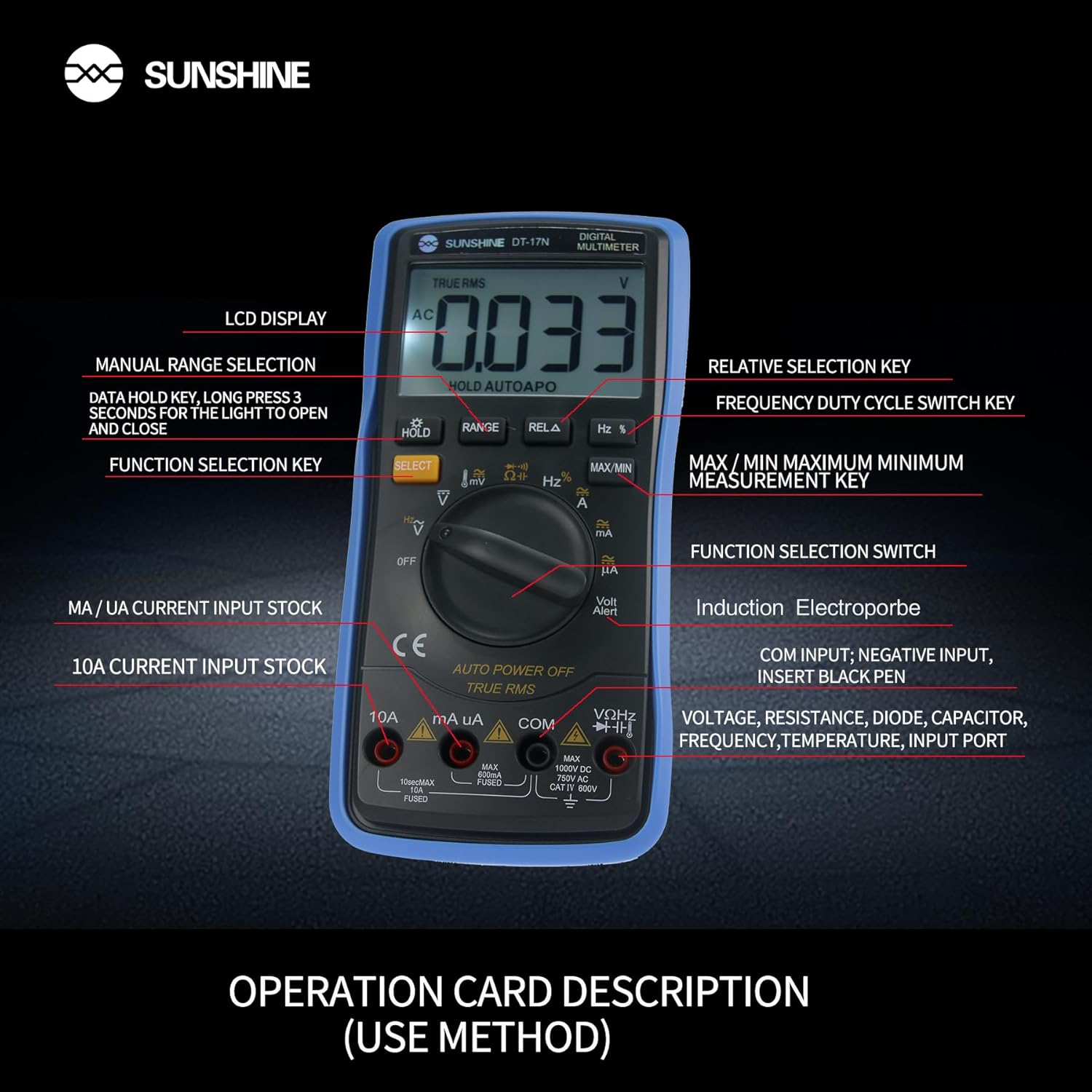
Figure 4: Detailed view of the multimeter's controls and input ports with their respective functions.
- Rotary Function Switch: Used to select the desired measurement function (e.g., Voltage, Current, Resistance, Temperature).
- SELECT Button: Toggles between different measurement modes within a single rotary switch position (e.g., AC/DC voltage, Diode/Continuity).
- HOLD Button: Freezes the current reading on the display. Press and hold to activate/deactivate the backlight.
- RANGE Button: Allows manual selection of measurement ranges, overriding the automatic ranging feature.
- RELA Button (Relative Selection Key): Measures the difference between a stored reference value and the current reading.
- Hz % Button (Frequency Duty Cycle Switch Key): Toggles between frequency and duty cycle measurements.
- MAX/MIN Button: Displays the maximum or minimum measured value during a measurement session.
- VΩHz Input Port: Connect the red test lead for voltage, resistance, frequency, capacitance, diode, and temperature measurements.
- COM Input Port: Connect the black test lead (common ground) for all measurements.
- mA/uA Input Port: Connect the red test lead for measuring small currents (milliamperes and microamperes).
- 10A Input Port: Connect the red test lead for measuring large currents (up to 10 Amperes).
- Volt Alert (NCV): Non-Contact Voltage detection feature.
4. Setup
4.1. Battery Installation
The DT-17N is battery-powered. To install or replace the battery:
- Ensure the multimeter is turned OFF.
- Locate the battery compartment cover on the back of the unit.
- Unscrew the retaining screw(s) and remove the cover.
- Insert the new battery, observing correct polarity (+ and -).
- Replace the battery compartment cover and secure it with the screw(s).
4.2. Connecting Test Leads
Always connect the black test lead to the COM input jack. Connect the red test lead to the appropriate input jack based on the measurement you intend to perform:
- For Voltage, Resistance, Capacitance, Frequency, Diode, and Temperature measurements: Connect the red test lead to the VΩHz jack.
- For Current measurements (mA/uA): Connect the red test lead to the mA/uA jack.
- For High Current measurements (10A): Connect the red test lead to the 10A jack.
5. Operating Instructions
The Sunshine DT-17N features automatic identification for most ranges, simplifying operation. Use the rotary switch to select the primary function and the SELECT button to toggle sub-functions.
5.1. Measuring Voltage (AC/DC)
- Turn the rotary switch to the V position.
- If necessary, press the SELECT button to toggle between AC (~) and DC (—) voltage.
- Connect the black test lead to the COM jack and the red test lead to the VΩHz jack.
- Connect the test probes in parallel to the circuit or component you wish to measure.
- Read the voltage value on the display.

Figure 5: The multimeter showing a DC millivolt measurement on its display.
5.2. Measuring Current (AC/DC)
Caution: Never connect the multimeter in parallel when measuring current, as this can damage the meter and the circuit. Always connect in series.
- Turn the rotary switch to the mA/uA or 10A position, depending on the expected current.
- If necessary, press the SELECT button to toggle between AC (~) and DC (—) current.
- Connect the black test lead to the COM jack. Connect the red test lead to the mA/uA or 10A jack accordingly.
- Open the circuit and connect the test probes in series with the load.
- Read the current value on the display.
5.3. Measuring Resistance
- Turn the rotary switch to the Ω position.
- Connect the black test lead to the COM jack and the red test lead to the VΩHz jack.
- Ensure the circuit is de-energized and all capacitors are discharged.
- Connect the test probes across the component to measure its resistance.
- Read the resistance value on the display.
5.4. Measuring Capacitance
- Turn the rotary switch to the Capacitance symbol (often shared with diode/continuity).
- Press the SELECT button until the capacitance mode is active.
- Connect the black test lead to the COM jack and the red test lead to the VΩHz jack.
- Ensure the capacitor is fully discharged before connecting the test probes.
- Connect the test probes across the capacitor.
- Read the capacitance value on the display.
5.5. Measuring Frequency / Duty Cycle
- Turn the rotary switch to the Hz % position.
- Press the Hz % button to toggle between frequency (Hz) and duty cycle (%).
- Connect the black test lead to the COM jack and the red test lead to the VΩHz jack.
- Connect the test probes in parallel to the signal source.
- Read the frequency or duty cycle value on the display.
5.6. Temperature Measurement
The DT-17N can measure temperature using a K-type thermocouple (not always included, check package contents).

Figure 6: Example of temperature measurement using the DT-17N Multimeter with a thermocouple.
- Turn the rotary switch to the °C/°F position.
- If necessary, press the SELECT button to choose between Celsius or Fahrenheit.
- Connect the K-type thermocouple to the VΩHz and COM jacks, observing polarity.
- Place the thermocouple tip on or in the object whose temperature you wish to measure.
- Read the temperature value on the display.
5.7. Diode Test and Continuity
- Turn the rotary switch to the Diode/Continuity symbol.
- Press the SELECT button to toggle between Diode Test and Continuity Test.
- Connect the black test lead to the COM jack and the red test lead to the VΩHz jack.
- For Diode Test: Connect the probes across the diode. The display will show the forward voltage drop. Reverse the probes to check for open circuit.
- For Continuity Test: Connect the probes across the circuit or component. A beep indicates continuity (low resistance).
5.8. Non-Contact Voltage (NCV) Detection
The NCV function allows detection of AC voltage without direct contact with conductors.
- Turn the rotary switch to the NCV position (often indicated by a Volt Alert symbol).
- Move the top part of the multimeter near the conductor.
- The meter will beep and/or flash an indicator light if AC voltage is detected.
5.9. Data Hold and Backlight
- Data Hold: Press the HOLD button briefly to freeze the current reading on the display. Press again to release.
- Backlight: Press and hold the HOLD button for approximately 3 seconds to turn the display backlight ON or OFF.
5.10. MAX/MIN Measurement
This function records the maximum and minimum values measured during a session.
- Select the desired measurement function (e.g., Voltage).
- Press the MAX/MIN button. The display will show 'MAX' and the maximum value recorded.
- Press MAX/MIN again to cycle to 'MIN' and view the minimum value.
- Press and hold MAX/MIN to exit this mode.
6. Maintenance
Proper maintenance ensures the longevity and accuracy of your multimeter.
6.1. Cleaning
Wipe the case with a damp cloth and mild detergent. Do not use abrasives or solvents. Ensure the meter is completely dry before use.
6.2. Battery Replacement
Refer to Section 4.1 for battery replacement instructions. Always use the specified battery type.
6.3. Holster Care
The multimeter is protected by a thick rubber shockproof holster, designed for durability and a non-slip grip. Keep the holster clean and free from debris.

Figure 7: The durable rubber holster provides protection and a comfortable grip for the multimeter.
7. Troubleshooting
If you encounter issues with your DT-17N multimeter, refer to the table below for common problems and solutions.
| Problem | Possible Cause | Solution |
|---|---|---|
| No display or dim display | Low or dead battery; Poor battery contact | Replace battery; Check battery contacts |
| Incorrect readings | Wrong function selected; Improper test lead connection; Damaged test leads; Out of range | Select correct function; Ensure leads are in correct jacks; Replace leads; Select higher range or check specifications |
| No continuity beep | Circuit resistance too high; Continuity mode not selected | Ensure resistance is below threshold; Press SELECT to enter continuity mode |
| Fuse blown (for current measurements) | Overcurrent applied | Replace fuse with specified type and rating; Ensure correct current measurement procedure |
8. Specifications
Technical specifications for the Sunshine DT-17N Digital Multimeter.
| Feature | Specification |
|---|---|
| Model | DT-17N |
| Measurement Type | Multimeter |
| Display | 5999 (5 5/6) counts, Automatic Polarity Display, Backlit LCD |
| Sampling Rate | Approximately 3 times per second |
| Power Source | Battery Powered |
| Minimum Operating Voltage | 3 Volts (DC) |
| Temperature Measurement Range | 0°C to 1000°C (32°F to 1832°F) |
| Induction Electroprobe Function | Yes (NCV) |
| Double Integral A/D Conversion | Yes |
| Item Dimensions | 5.51 x 2.76 x 1.18 inches |
| Item Weight | 0.55 Kilograms |
| Color | Blue |
9. Warranty and Support
9.1. Warranty Information
This product comes with a warranty of 3 months from the date of purchase. Please retain your proof of purchase for warranty claims. The warranty covers manufacturing defects under normal use.
9.2. Customer Support
For technical assistance or inquiries regarding your Sunshine DT-17N Digital Multimeter, please contact your retailer or the manufacturer's customer service department. Refer to your purchase documentation for specific contact details.


