
1. Introduction
This manual provides detailed instructions for the installation, operation, and maintenance of your VST BT13 6.56ft Motion Sensor LED Strip Light. Please read this manual thoroughly before use to ensure proper function and longevity of the product.
2. Product Overview
2.1 Components
- LED Strip Light (6.56ft / 2m)
- Motion Sensor Controller
- USB Cable
- Velcro Tape for Installation
- Note: 4 AAA batteries are required but not included.

Image 2.1: Controller Diagram. This image illustrates the main components of the LED strip light controller, including the LED strip connection, Auto/PIR mode switch, Manual mode, PIR sensor, ON/OFF button, USB port, and battery compartment for 4 AAA batteries.
2.2 Key Features
- Dual Mode Operation: Choose between automatic motion sensing or continuous manual operation.
- Flexible Power Options: Can be powered by 4 AAA batteries or a USB cable.
- Easy Installation: Utilizes Velcro tape for simple and repositionable mounting.
- High-Quality Illumination: Features 60 LEDs per meter, 6500K cool white light, and a Color Rendering Index (CRI) greater than 80.
3. Specifications
| Feature | Specification |
|---|---|
| Model Number | BT13 |
| Light Source Type | LED |
| Color Temperature | 6500 Kelvin (Cool White) |
| Strip Length | 6.56 feet (2 meters) |
| Wattage | 4 Watts |
| Voltage | 3V DC |
| Power Source | 4 AAA Batteries (not included) or USB Cable |
| Mounting Type | Velcro Tape Installation |
| Material | Acrylonitrile Butadiene Styrene (ABS) |
| Item Weight | 0.25 kg |
| Certifications | CE |
4. Setup & Installation
4.1 Preparing the Surface
- Ensure the installation surface is clean, dry, and smooth. Dust, oil, or moisture can affect adhesive performance.
4.2 Attaching the Controller
- Peel off the protective backing from one side of the Velcro tape.
- Apply this side firmly to the back of the motion sensor controller.
- Peel off the remaining protective backing from the Velcro tape.
- Press the controller firmly onto your desired installation surface.
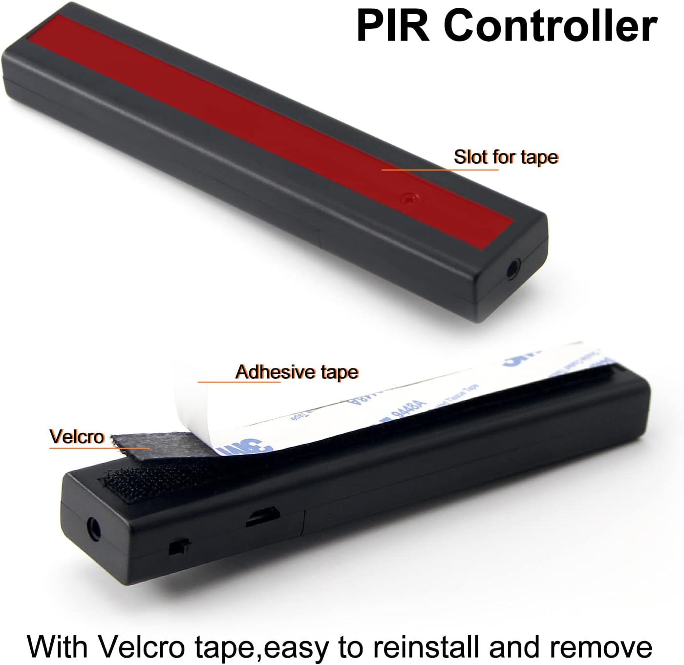
Image 4.1: Velcro Tape Installation. This image demonstrates the process of attaching the Velcro tape to the PIR controller for easy installation and removal.

Image 4.2: Adhesive Backing. A close-up view of peeling the protective layer from the adhesive side of the Velcro tape.
4.3 Attaching the LED Strip
- Connect the LED strip to the controller.
- Peel off the adhesive backing from the LED strip.
- Carefully press the LED strip along your desired path. Ensure it adheres firmly.
- The LED strip can be cut at designated marks to fit specific lengths. Refer to the cutting marks on the strip.

Image 4.3: LED Strip Detail. This image shows the individual LEDs on the strip and indicates where it can be safely cut to adjust length.

Image 4.4: Cuttable LED Strip. This image highlights the designated cutting points on the LED strip for customization.

Image 4.5: Flexible LED Strip. This image demonstrates the flexibility of the LED strip, allowing it to be installed around corners or curved surfaces.
5. Power Supply Options
The VST BT13 LED Strip Light offers two power supply methods:
5.1 Battery Power (4 x AAA)
- Open the battery compartment on the controller.
- Insert 4 AAA batteries, ensuring correct polarity (+/-).
- Close the battery compartment securely.

Image 5.1: Battery Installation. This image shows the process of inserting 4 AAA batteries into the controller's battery compartment.

Image 5.2: Battery Powered. The controller with batteries installed, ready for use.
5.2 USB Cable Power
- Connect the provided USB cable to the USB port on the controller.
- Plug the other end of the USB cable into a compatible USB power adapter (e.g., phone charger, power bank, computer USB port).
- Note: The USB cable does not have a power storage function; it must be connected to a power source to operate the light.

Image 5.3: USB Power Connection. The controller connected to a USB power adapter via the provided USB cable.
6. Operating Instructions
The VST BT13 LED Strip Light features two operating modes:
6.1 Auto Mode (Motion Sensor)
- Slide the switch on the controller to the "Auto" position.
- In this mode, the light will automatically turn on when motion is detected within a sensing distance of up to 2.5 meters.
- The light will remain on for approximately 30 seconds after motion ceases, then turn off automatically.

Image 6.1: Motion Sensor Detection. This diagram shows the 120-degree detection angle and 2-3 meter sensing range of the motion sensor.
6.2 Manual Mode (Continuous On/Off)
- Slide the switch on the controller to the "Man" position.
- In this mode, the motion sensor is deactivated.
- Press the ON/OFF button to manually turn the light on or off.
6.3 Video Guide: Unpacking and Utilization
Video 6.1: BT13 Unpacking and Utilization. This official video from VST Lighting US demonstrates the unpacking process and basic utilization of the BT13 LED strip light, including power options and mode selection.
7. Applications
The versatile design of the VST BT13 LED Strip Light makes it suitable for various indoor applications, providing convenient and efficient lighting:
- Closets and Wardrobes
- Under Counter and Cabinet Lighting
- Stairways and Hallways
- Bedrooms and Baby Rooms
- Bookshelves and Display Cases
- Garages and Basements
- Pantries and Trunks

Image 7.1: Diverse Applications. This image displays the LED strip light used in various settings such as kitchens, wardrobes, and motorhomes, highlighting its adaptability.

Image 7.2: Home Lighting Solutions. This image illustrates the LED strip light providing illumination in different home environments, including under beds, in kitchens, and inside closets.
8. Maintenance
- Cleaning: Use a soft, dry cloth to gently wipe the LED strip and controller. Avoid using abrasive cleaners or excessive moisture.
- Battery Replacement: If using battery power, replace all 4 AAA batteries simultaneously when the light dims or stops functioning. Do not mix old and new batteries or different battery types.
- Adhesive Longevity: If the adhesive tape loses its stickiness over time, you can re-secure the strip with new double-sided adhesive tape or the Velcro tape provided.
9. Troubleshooting
| Problem | Possible Cause | Solution |
|---|---|---|
| Light does not turn on. | No power supply. | Ensure batteries are correctly inserted or USB cable is connected to a working power source. |
| Light is dim or flickers. | Low battery power. | Replace all 4 AAA batteries with new ones. |
| Motion sensor not working in Auto mode. | Controller is in Manual mode. | Slide the switch to the "Auto" position. |
| Motion sensor is too sensitive or not sensitive enough. | Environmental factors or sensor placement. | Adjust the position of the controller to optimize detection range. Avoid placing near heat sources or direct sunlight. |
| LED strip not adhering properly. | Surface is dirty or adhesive has worn out. | Clean the surface thoroughly. Reapply with new adhesive or use the Velcro tape. |
10. Warranty & Support
10.1 Manufacturer Warranty
This VST product is covered by a 2-year manufacturer's warranty from the date of purchase. This warranty covers defects in materials and workmanship under normal use. It does not cover damage caused by misuse, accidents, unauthorized modifications, or improper installation.
10.2 Customer Support
For any questions, technical assistance, or warranty claims, please contact VST customer support through the retailer where the product was purchased or visit the official VST website for contact information.
